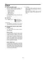
1 - 149
OTHER ADJUSTMENT
1 ADJUSTMENT
Step
Operation
1
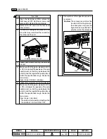
Set paper into the tray and make a copy
(required to place the paper stopper at its
HP position).
2
Open the front door of the FNS and draw
out the conveyance unit.
3
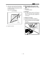
Make sure that the distance between the
edge of the guide plate and the paper stop-
per is within the specification range.
Spec range: A = 20
±
0.5mm
If the distance is outside the spec range,
adjust according to the instructions de-
scribed in the following step.
4
Loosen the screws holding the pulleys and
adjust the distance by rotating the pulleys.
Tighten the screws.
Note:
Do not rotate the shaft on which the
pulleys are attached. If it is rotated
for some reason, the stopper is
placed out of its HP position. Then
perform the procedure again from
Step 1.
[38] Adjusting the Position of the PZ 2nd
Folding Stopper
Caution:
This adjustment affects the 2nd folding
skew. Therefore, first complete this
adjustment and then proceed to the
[39] Adjusting the PZ 2nd Folding
Skew section.
1.
Tools
• Screwdriver (Phillips)
• Hex wrench
2.
Adjustment Method
A
Hex, screw
Pulley
Pulley
Guide
plate
Paper
stopper
Hex, screw
2nd foldng
stopper
2nd folding
stopper
Shaft
A = 20
±
0.5mm
METHOD
ADDITION
MODEL
7075
MANUAL
SERVICE HANDBOOK
REVISED EDITION
DATE
Sep. 2001
PAGE
1-149
Содержание 7075/FORCE 75
Страница 1: ...FEBRUARY 2003 CSM 7075 F75 7085 F85 SERVICE MANUAL MODELS 7075 FORCE 75 7085 FORCE 85...
Страница 2: ......
Страница 3: ...7075 FORCE 75 7085 FORCE 85 SERVICE MANUAL FEBRUARY 2003...
Страница 39: ...OUTLINE 1...
Страница 40: ...Blank page...
Страница 55: ...1 15 MAIN BODY 11 Paper Exit Drive Section FRONT Paper exit roller Paper exit motor M10...
Страница 56: ...1 16 MAIN BODY 12 Toner Supply Drive Toner supply motor 1 M11 FRONT Toner supply motor 2 M15 Toner cartridge...
Страница 58: ...1 18 MAIN BODY 14 Web Drive Section FRONT Web drive motor M16 Cleaning web...
Страница 59: ...UNIT EXPLANATION 2...
Страница 60: ...Blank page...
Страница 62: ...2 A 2 EXTERNAL SECTION Blank page...
Страница 120: ...2 K 6 TRAY 3 PAPER FEED UNIT Blank page...
Страница 126: ...2 L 6 BY PASS TRAY Blank page...
Страница 130: ...2 M 4 VERTICAL PAPER CONVEYANCE SECTION Blank page...
Страница 154: ...2 O 8 FIXING UNIT Blank page...
Страница 165: ...DISASSEMBLY ASSEMBLY 3...
Страница 216: ...3 H 4 TONER SUPPLY UNIT Blank page...
Страница 224: ...3 I 8 CLEANING TONER RECYCLE UNIT Blank page...
Страница 232: ...3 J 8 PAPER FEED UNITS OF TRAYS 1 AND 2 Blank page...
Страница 240: ...3 K 8 TRAY 3 PAPER FEED UNIT Blank page...
Страница 292: ...3 O 18 FIXING UNIT Blank page 3 O 16...
Страница 293: ...MODELS 7075 FORCE 75 7085 FORCE 85 SERVICE SECTION FEBRUARY 2003...
Страница 294: ......
Страница 315: ...ADJUSTMENT 1...
Страница 316: ......
Страница 343: ...1 19 25 ADJUSTMENT Blank page 1 19 2...
Страница 372: ...1 44 25 ADJUSTMENT 1 ADJUSTMENT Blank page...
Страница 458: ...1 114 OTHER ADJUSTMENT Blank page 1 112 2...
Страница 497: ...ISW 2...
Страница 498: ......
Страница 511: ...SERVICE 3...
Страница 512: ......
Страница 514: ...Blank page...
Страница 550: ...3 18 SERVICE Blank page...
Страница 551: ...ELECTRICAL PARTS LIST WIRING DIAGRAMS 4...
Страница 552: ......
Страница 610: ...4 40 Blank page METHOD ADDITION MODEL 7075 7085 MANUAL SERVICE HANDBOOK REVISED EDITION 3 DATE Jan 2002 PAGE 4 34 6...
Страница 611: ...JAM ERROR CODE LIST 5...
Страница 612: ......
Страница 625: ...5 13 JAM CODE LIST Blank page 5 11 2...
Страница 659: ...TIMING CHARTS 6...
Страница 660: ......
Страница 678: ...6 18 TIMING CHARTS Blank page...
Страница 679: ...INSTALLATION INSTRUCTIONS 7...
Страница 680: ......
Страница 692: ...Blank page...
Страница 704: ...Blank page...
Страница 724: ...Blank page...
Страница 730: ...Blank page...
Страница 736: ...Blank page...
Страница 758: ...Blank page...
Страница 780: ...Blank page...
Страница 832: ...Blank page...
Страница 833: ...APPENDIX 7085 OVERALL WIRING DIAGRAM...
Страница 834: ......

