


PFX2512_CE
25
Connection and Setting of the Each Equipment
2
In
st
al
la
ti
on
a
n
d P
re
p
ar
a
ti
o
n
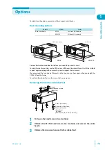
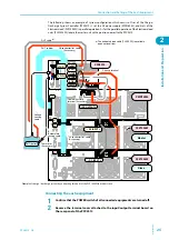
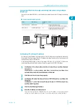
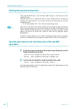
The following shows an example of system configuration which consist of 1set of the Charge/
Discharge System Controller (PFX2512), 1 set the DC power supply (PWR1600L), and 2sets of the
Electronic load (PLZ1004W) in parallel operation. As for the parallel operation of the Electronic load
units (PLZ1004W), locate the master unit with a position nearest to the PFX2512.
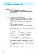
Connecting the each equipment
1
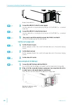
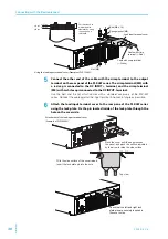
Confirm that the POWER switch of all connected equipments are turned off.
2
Remove the terminal cover attached to the input/output terminal board on
the rear panel of the PFX2512.
–
+
TP-BUS
NC02087-2
J1
100-240V 50-60Hz
2600VA MAX
AC INPUT
PLZ1004W
Master
Slave
PLZ1004W
PWR1600L
PFX2512
– DC
– DC INPUT +
– DC INPUT +
J1
J2
J1
J1
–
+
–
+
DUT cable
DUT cable
26-conductor flat cable
(Accessory)
Voltage
sensing
cable
Temperature
sensing cable
DUT (battery)
Cable with crimp
terminal (Accessory)
20-conductor flat cable
(Accessory)
Chassis terminal
Thermistor
(Accessory)
To PWR J1
To PLZ J1
To PWR +
To PWR
–
To DUT +
To DUT
–
To PLZ +
To PLZ
–
The dedicated load cable (TL08-PFX) is available
as an optional item.
*
*
*
Example of charge / discharge system by connecting two units of the PLZ1004W in master-slave
Содержание PFX2515
Страница 10: ...10 PFX2512_CE This page is intentionally blank ...
Страница 11: ...General Description This chapter describes the outline of product the connectable equipments and the options ...
Страница 58: ...58 PFX2512_CE This page is intentionally blank ...
Страница 59: ...Specification This chapter contains the PFX2512 specifications and outline drawings ...
Страница 86: ...86 PFX2512_CE This page is intentionally blank ...
Страница 100: ...100 PFX2512_CE This page is intentionally blank ...
Страница 103: ......