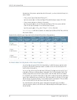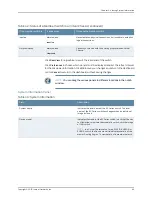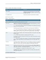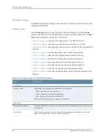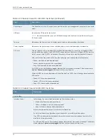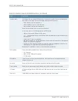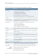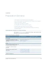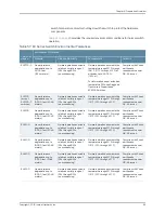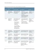
Table 48: Chassis Viewer for EX3200, EX3300, and EX4200 Switches
(continued)
Description
Field
Indicates the USB port for the switch.
NOTE:
We recommend that you use USB flash drives purchased from Juniper Networks for your
EX Series switch.
USB port
The management port is used to connect the switch to a management device for out-of-band
management.
Management (
me0
) port
The console port is used to connect the switch to a management console or to a console server.
(You might do this for initial switch configuration.)
Console port
Mouse over the power supply icons to display name, status, and description information.
Power supplies
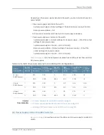
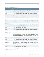
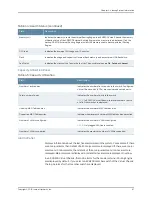
Table 49: Chassis Viewer for EX4300 Switches
Description
Field
Front View
In the image, the colors listed below denote the interface status for both copper and fiber media
type of ports:
•
Green—Interface is up and operational.
•
Yellow—Interface is up but is nonoperational.
•
Gray—Interface is down and nonoperational.
Mouse over the interface (port) to view more information.
Interface status
LCD panel configured for the LEDs on the ports. Mouse over the icon to view the current character
display.
LCD panel
The mini console port is used to connect the switch to the management console.
Mini USB console
You can install an uplink module in the PIC 2 slot. Mouse over the ports in the module to view the
details of the ports in module.
24-port and 48-port EX4300 switches support the4-port 10-Gigabit SFP+ uplink module.
EX4300-32F switches support the 2-port 40-Gigabit QSFP+ uplink module and the 8-port 10-Gigabit
SFP+ uplink module.
When you install a transceiver in the port, the following colors denote the interface status:
•
Green—Interface is up and operational.
•
Yellow—Interface is up but is not operational.
•
Gray—Interface is down and not operational.
PIC 2 slot
NOTE:
In EX4300 switches the LEDs are seen in the front panel, these are not active.
Rear View of the EX4300 Switch
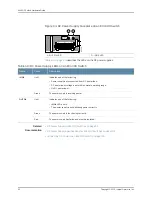
The management port is used to connect the switch to a management device for out-of-band
management.
Management port
71
Copyright © 2015, Juniper Networks, Inc.
Chapter 5: Viewing System Information
Содержание EX4300
Страница 1: ...EX4300 Switch Hardware Guide Modified 2015 06 29 Copyright 2015 Juniper Networks Inc ...
Страница 16: ...Copyright 2015 Juniper Networks Inc xvi EX4300 Switch Hardware Guide ...
Страница 22: ...Copyright 2015 Juniper Networks Inc xxii EX4300 Switch Hardware Guide ...
Страница 24: ...Copyright 2015 Juniper Networks Inc 2 EX4300 Switch Hardware Guide ...
Страница 102: ...Copyright 2015 Juniper Networks Inc 80 EX4300 Switch Hardware Guide ...
Страница 104: ...Copyright 2015 Juniper Networks Inc 82 EX4300 Switch Hardware Guide ...
Страница 128: ...Copyright 2015 Juniper Networks Inc 106 EX4300 Switch Hardware Guide ...
Страница 172: ...Copyright 2015 Juniper Networks Inc 150 EX4300 Switch Hardware Guide ...
Страница 176: ...Copyright 2015 Juniper Networks Inc 154 EX4300 Switch Hardware Guide ...
Страница 218: ...Copyright 2015 Juniper Networks Inc 196 EX4300 Switch Hardware Guide ...
Страница 236: ...Copyright 2015 Juniper Networks Inc 214 EX4300 Switch Hardware Guide ...
Страница 238: ...Copyright 2015 Juniper Networks Inc 216 EX4300 Switch Hardware Guide ...
Страница 250: ...Copyright 2015 Juniper Networks Inc 228 EX4300 Switch Hardware Guide ...
Страница 256: ...Copyright 2015 Juniper Networks Inc 234 EX4300 Switch Hardware Guide ...
Страница 277: ...PART 5 Troubleshooting Alarms and Syslog Messages on page 257 255 Copyright 2015 Juniper Networks Inc ...
Страница 278: ...Copyright 2015 Juniper Networks Inc 256 EX4300 Switch Hardware Guide ...
Страница 286: ...Copyright 2015 Juniper Networks Inc 264 EX4300 Switch Hardware Guide ...
Страница 292: ...Copyright 2015 Juniper Networks Inc 270 EX4300 Switch Hardware Guide ...
Страница 306: ...Copyright 2015 Juniper Networks Inc 284 EX4300 Switch Hardware Guide ...
Страница 312: ...Copyright 2015 Juniper Networks Inc 290 EX4300 Switch Hardware Guide ...
Страница 336: ...Copyright 2015 Juniper Networks Inc 314 EX4300 Switch Hardware Guide ...


