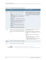
Table 91: Viewing System Log Messages
(continued)
Additional Information
Function
Field
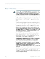
A severity level indicates how seriously the triggering
event affects switch functions. When you configure a
location for logging a facility, you also specify a severity
level for the facility. Only messages from the facility
that are rated at that level or higher are logged to the
specified file.
Severity level of a message is indicated by different
colors.
•
Unknown
—Gray—Indicates no severity level is
specified.
•
Debug/Info/Notice
—Green—Indicates conditions that
are not errors but are of interest or might warrant
special handling.
•
Warning
—Yellow—Indicates conditions that warrant
monitoring.
•
Error
—Blue—Indicates standard error conditions that
generally have less serious consequences than errors
in the emergency, alert, and critical levels.
•
Critical
—Pink—Indicates critical conditions, such as
hard-drive errors.
•
Alert
—Orange—Indicates conditions that require
immediate correction, such as a corrupted system
database.
•
Emergency
—Red—Indicates system panic or other
conditions that cause the switch to stop functioning.
Severity
The event ID begins with a prefix that indicates the
generating software process.
Some processes on a switch do not use codes. This
field might be blank in a message generated from such
a process.
An event can belong to one of the following type
categories:
•
Error
—Indicates an error or failure condition that
might require corrective action.
•
Event
—Indicates a condition or occurrence that does
not generally require corrective action.
Displays a code that uniquely identifies the message.
The prefix on each code identifies the message source,
and the rest of the code indicates the specific event or
error.
Event ID
Displays a more detailed explanation of the message.
Event
Description
Displays the time at which the message was logged.
Time
Related
Documentation
•
Checking Active Alarms with the J-Web Interface on page 258
•
Understanding Alarm Types and Severity Levels on EX Series Switches on page 257
Copyright © 2015, Juniper Networks, Inc.
262
EX4300 Switch Hardware Guide
Содержание EX4300
Страница 1: ...EX4300 Switch Hardware Guide Modified 2015 06 29 Copyright 2015 Juniper Networks Inc ...
Страница 16: ...Copyright 2015 Juniper Networks Inc xvi EX4300 Switch Hardware Guide ...
Страница 22: ...Copyright 2015 Juniper Networks Inc xxii EX4300 Switch Hardware Guide ...
Страница 24: ...Copyright 2015 Juniper Networks Inc 2 EX4300 Switch Hardware Guide ...
Страница 102: ...Copyright 2015 Juniper Networks Inc 80 EX4300 Switch Hardware Guide ...
Страница 104: ...Copyright 2015 Juniper Networks Inc 82 EX4300 Switch Hardware Guide ...
Страница 128: ...Copyright 2015 Juniper Networks Inc 106 EX4300 Switch Hardware Guide ...
Страница 172: ...Copyright 2015 Juniper Networks Inc 150 EX4300 Switch Hardware Guide ...
Страница 176: ...Copyright 2015 Juniper Networks Inc 154 EX4300 Switch Hardware Guide ...
Страница 218: ...Copyright 2015 Juniper Networks Inc 196 EX4300 Switch Hardware Guide ...
Страница 236: ...Copyright 2015 Juniper Networks Inc 214 EX4300 Switch Hardware Guide ...
Страница 238: ...Copyright 2015 Juniper Networks Inc 216 EX4300 Switch Hardware Guide ...
Страница 250: ...Copyright 2015 Juniper Networks Inc 228 EX4300 Switch Hardware Guide ...
Страница 256: ...Copyright 2015 Juniper Networks Inc 234 EX4300 Switch Hardware Guide ...
Страница 277: ...PART 5 Troubleshooting Alarms and Syslog Messages on page 257 255 Copyright 2015 Juniper Networks Inc ...
Страница 278: ...Copyright 2015 Juniper Networks Inc 256 EX4300 Switch Hardware Guide ...
Страница 286: ...Copyright 2015 Juniper Networks Inc 264 EX4300 Switch Hardware Guide ...
Страница 292: ...Copyright 2015 Juniper Networks Inc 270 EX4300 Switch Hardware Guide ...
Страница 306: ...Copyright 2015 Juniper Networks Inc 284 EX4300 Switch Hardware Guide ...
Страница 312: ...Copyright 2015 Juniper Networks Inc 290 EX4300 Switch Hardware Guide ...
Страница 336: ...Copyright 2015 Juniper Networks Inc 314 EX4300 Switch Hardware Guide ...


