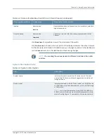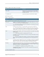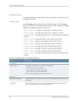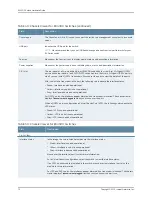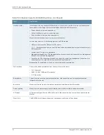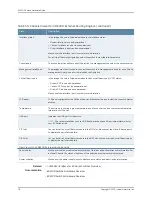
Table 44: Health Status
(continued)
Description
Field
Indicates the memory used in the external Routing Engine. In an EX8200 Virtual Chassis, the memory
utilization value of the XRE200 External Routing Engine in the master role is displayed. Click the
backup XRE200 External Routing Engine to view the memory used in backup external Routing
Engine.
Memory util.
Indicates the average CPU usage over 15 minutes.
CPU load
Indicates the usage and capacity of internal flash memory and any external USB flash drive.
Flash
Indicates the status of the fans in the fan tray. The possible values are
OK
,
Failed
, and
Absent
.
Fan Status
Capacity Utilization Panel
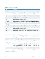
Table 45: Capacity Utilization
Description
Field
Indicates the number of active ports in the switch. Configured
Virtual Chassis ports (VCPs) are considered as active ports.
Number of active ports
Indicates the number of ports in the switch.
NOTE:
In EX3300 Virtual Chassis, the total number of ports
of all of the switches is displayed.
Total number of ports
Indicates the number of MAC table entries.
Used-up MAC-Table entries
Indicates the maximum number of MAC table entries permitted.
Supported MAC-Table entries
Indicates the number of VLANs configured.
NOTE:
Only tagged VLANs are counted.
Number of VLANs configured
Indicates the maximum number of VLANs supported.
Number of VLANs supported
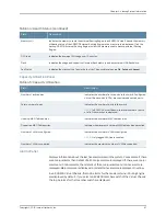
Alarms Panel
Displays information about the last five alarms raised in the system. For example, if there
are 5 major alarms, then details of all 5 major alarms are displayed. If there are 4 major
alarms and 3 minor alarms, then details of the 4 major alarms and 1 minor alarm are
displayed. Major alarms are displayed in red and minor alarms are displayed in yellow.
In an EX8200 Virtual Chassis, the top 5 alarms for the master external Routing Engine
are displayed by default. If you select an EX8200 member switch of the Virtual Chassis,
the top 5 alarms for that member switch are displayed.
67
Copyright © 2015, Juniper Networks, Inc.
Chapter 5: Viewing System Information
Содержание EX4300
Страница 1: ...EX4300 Switch Hardware Guide Modified 2015 06 29 Copyright 2015 Juniper Networks Inc ...
Страница 16: ...Copyright 2015 Juniper Networks Inc xvi EX4300 Switch Hardware Guide ...
Страница 22: ...Copyright 2015 Juniper Networks Inc xxii EX4300 Switch Hardware Guide ...
Страница 24: ...Copyright 2015 Juniper Networks Inc 2 EX4300 Switch Hardware Guide ...
Страница 102: ...Copyright 2015 Juniper Networks Inc 80 EX4300 Switch Hardware Guide ...
Страница 104: ...Copyright 2015 Juniper Networks Inc 82 EX4300 Switch Hardware Guide ...
Страница 128: ...Copyright 2015 Juniper Networks Inc 106 EX4300 Switch Hardware Guide ...
Страница 172: ...Copyright 2015 Juniper Networks Inc 150 EX4300 Switch Hardware Guide ...
Страница 176: ...Copyright 2015 Juniper Networks Inc 154 EX4300 Switch Hardware Guide ...
Страница 218: ...Copyright 2015 Juniper Networks Inc 196 EX4300 Switch Hardware Guide ...
Страница 236: ...Copyright 2015 Juniper Networks Inc 214 EX4300 Switch Hardware Guide ...
Страница 238: ...Copyright 2015 Juniper Networks Inc 216 EX4300 Switch Hardware Guide ...
Страница 250: ...Copyright 2015 Juniper Networks Inc 228 EX4300 Switch Hardware Guide ...
Страница 256: ...Copyright 2015 Juniper Networks Inc 234 EX4300 Switch Hardware Guide ...
Страница 277: ...PART 5 Troubleshooting Alarms and Syslog Messages on page 257 255 Copyright 2015 Juniper Networks Inc ...
Страница 278: ...Copyright 2015 Juniper Networks Inc 256 EX4300 Switch Hardware Guide ...
Страница 286: ...Copyright 2015 Juniper Networks Inc 264 EX4300 Switch Hardware Guide ...
Страница 292: ...Copyright 2015 Juniper Networks Inc 270 EX4300 Switch Hardware Guide ...
Страница 306: ...Copyright 2015 Juniper Networks Inc 284 EX4300 Switch Hardware Guide ...
Страница 312: ...Copyright 2015 Juniper Networks Inc 290 EX4300 Switch Hardware Guide ...
Страница 336: ...Copyright 2015 Juniper Networks Inc 314 EX4300 Switch Hardware Guide ...


