Doc. No.: 103839 Rev. A
jotron.com
Page 15 of 104
6.3
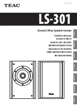
Display Unit
Front View
The Display unit is the user interface for the AIS system
on the bridge. It is used to configure the Transponder
and to present AIS data about own and other ships,
both graphically and in list form. The Display Unit
consists of a splash proof housing with a 7 inch LCD
colour display with touch screen. Splash proof
connections for Main and Backup power, Pilot plug and
Transponder (Ethernet) are present on the back side of
the unit. The internal power supply is switched in order
to obtain a high efficiency over the whole voltage input
range from 10.8V – 31.2V. A Backup power source can
be connected if available. This will be automatically
switched in if the main source of power is lost.
The main features of the Tron AIS Display Unit are:
Give the user information about other ships with AIS in the vicinity.
Enable the user to obtain information about other ships and send and receive safety messages to
other ships with AIS Transponders.
CPA/TCPA
Enable the user to configure the AIS System.
Alert the user about alarms from the AIS system.
Pilot Port connection directly to the Display Unit.
Certified to IP54 and IEC 60945 Ed.4 “Protected”.
Operating temperature from -25°C to +55°C and storage temperature from -30°C to +70°C
Rear View
Содержание 103660
Страница 1: ...Tron AIS TR 8000 MkII AIS Class A Inland AIS Transponder Operator and Installation Manual...
Страница 2: ......
Страница 103: ......