SECTION 3 - CHASSIS & TURNTABLE
31215031
3-21
13.
Insert Planet Shaft (4E) through first set of Thrust Wash-
ers (4B), Planet gear, then second set of Washers (4B).
Use an alignment punch or similar tool to align roll pin
holes on Spindle (1A) and Planet Shaft (4E).
NOTE:
Do not hit Planet Gears (4F) when driving in Roll Pins (4G).
14.
Drive new Roll Pin (4G) in aligned roll pin holes. Pin
should be flush with OD of spindle.
15.
Repeat Steps (11-14) for installation of two remaining
Planet Gears (4F).
Cover Sub-Assembly
1.
Grease O-Ring (6E) and insert in internal groove in Cover
(6A).
2.
Assemble Disengage Cap (6B) on Cover (6A) using two
Hex Head Bolts (6C). Torque bolts to 70-80 in-lb (7.9- 9
Nm).
3.
Insert Disengage Rod (6D) in hole in Cover (6A) until it
touches inside of Disengage Cap (6B).
NOTE:
Disengage Rod can be inserted either end first.
4.
Grease Face of Thrust Washer (2) and place in Cover (6A)
making sure tangs on washer seat into pockets in cover.
5.
Install O-Ring Pipe Plugs (6F) in Cover (6A). Plugs should
be hand tight.
Main Assembly
NOTE:
All components should receive a generous amount of lubri-
cant oil as they are being assembled.
1.
Place Hub-Spindle Sub-Assembly on bench.
2.
Grease O-Ring (18) and place it in groove of Hub (1D).
3.
Place Ring Gear (1E) on Hub (1D). Align three shipping
Capscrew Holes on Hub (1D) and Ring Gear (1E).
4.
Install three shipping Capscrews (19) in ring gear and
hub. Torque to 15-20 ft-lb (20-27 Nm).
5.
Place External Retaining Ring (5) over 13T spline to the
retaining groove on Input Shaft (9).
NOTE:
For ratio 48:1, assemble Output Sun Gear (11) over Input
Shaft (9) first, then install External Retaining Ring (5).
6.
Using appropriate tool to install Retaining Ring (20) in
groove on Output Sun (11).
7.
Place Input Shaft (9) spline end into mesh with Internal
Coupling (7) splines.
8.
With modified spline end facing up, place Output Gear
(11) in mesh with planet gears from Hub-Spindle Sub-
Assembly.
9.
Place Input Carrier Sub-Assembly (3A) on Output Sun
Gear (11) splines. Drop Input Sun (10) in mesh with
planet gears for specific ratios, if required. (No timing
required).
10.
Grease O-Ring (17) and insert in groove in Cover Sub-
Assembly (6).
11.
Install Cover Sub-Assembly (6) in Ring Gear (1E) counter-
bore and install Retaining Ring (6G) in groove in Ring
Gear (1E).
12.
Attach ID Tag (15) on unit using Drive Screws (16).
13.
Check disconnect, roll and air check unit, leak check
brake, and record release pressure.
14.
Insert Plastic Plug (12) if applicable.
Integral Brake Check
1.
Using appropriate fittings, connect hydraulic line from
hand pump to brake port.
2.
Check brake is set by trying to rotate Input Shaft (9). This
can be accomplished by installing an appropriate tool
(any tool that can locate on splines of Input Coupling (7),
such as a mating splined shaft) into Input Coupling (7).
3.
Bleed brake. Increase hydraulic pressure gradually while
trying to rotate input until brake just starts to release.
Note this pressure. Make sure pressure falls into appro-
priate range below.
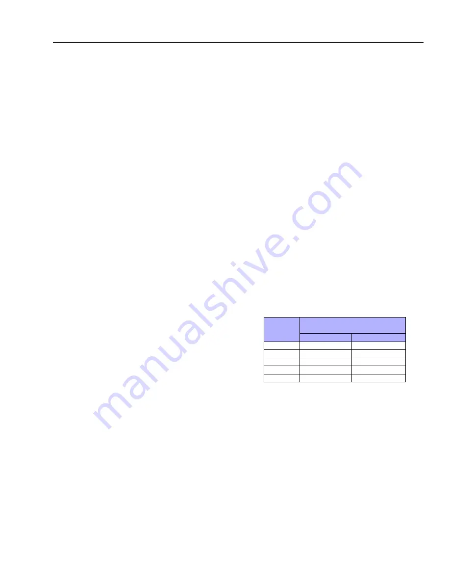
BRAKE
CODE
JUST RELEASE
PRESSURE RANGE
PSI
BAR
A
200-260
13.7-17.9
B
170-220
11.7-15.1
C
140-185
9.6-12.7
D
130-155
8.9-10.6
E
115-145
7.9-9.9
4.
Increase pressure to 1,000 psi and hold for 30 seconds to
check for leaks. Repair leaks if necessary.
NOTE:
Make sure brake re-engages when pressure is released.
NOTE:
When done, make sure Input Coupling (7) is centered in
Spindle (1A) to make installation of motor possible without
release of brake.
Go
to
Discount-Equipment.com
to
order
your
parts


