background image

www.javad.com

37

Collect Screens

Full Screen

Tap to get to the Full Screen mode where you can also turn 

on the camera and measure angles.

Zoom


Used to cycle the zoom mode between 

Zoom Auto Scale


which shows the extents of the map; 

1:1 Zoom

 mode which 

sets the display at a 1:1 scale factor and manually / arbitrarily 

setting the zoom level.

Center

This button centers the map on the current position.

Zoom In/Out


The 

Zoom IN

 and 

Zoom Out

 buttons are shown in the bottom 

right and left corners. They can be held down to zoom in 

and out faster. The “+” and “-” hardware buttons function the 

same.

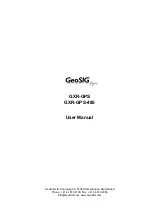
User Defined Boxes (Whiteboxes)


There are 10 

User Defined Boxes

 around the map.  Hold 

them down to select which items you wish to shown in 

them.  Tapping them allows you to enter a new value for 

the appropriate items, reset the statistics, take a picture etc.

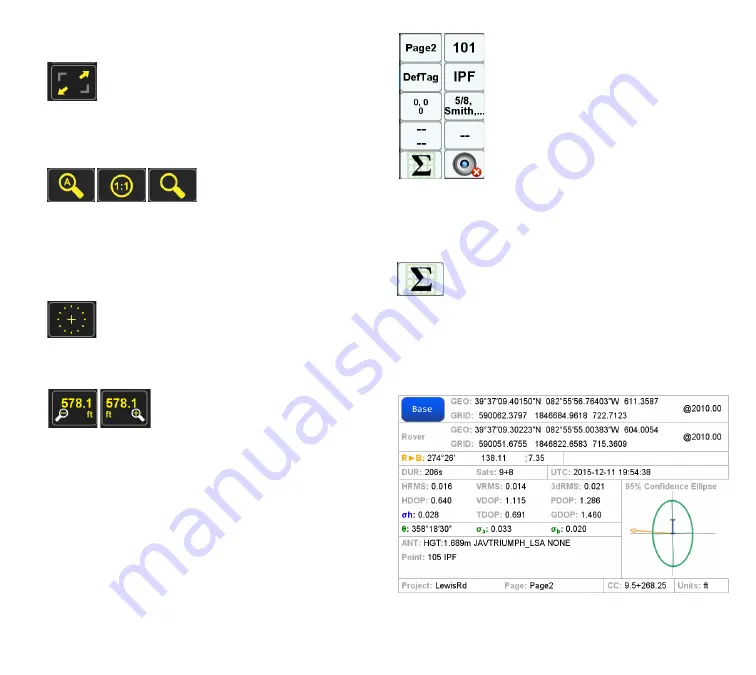
One of the configurable white boxes is the 

Base/Rover 

Statistic

. When doing RTK surveying, the associated screen 

can be called up with just tap.  It conveys a good deal of 

information pertaining the Base and Rover as seen in the 

example:

Reject / Accept

Содержание TRIUMPH-LS

Страница 1: ...U S E R S G U I D E TO T H E T R I U M P H L S E Version 20160121 ...

Страница 2: ...t 63 Creating Vertical Alignment 71 Defining Cross Sections 76 Entering Offset Points 79 Modifying the Alignment 80 Staking 81 Stake Settings 81 Stake Modes 87 Using ShapeTags and Codes 92 Data Structure 93 Defining ShapeTags Codes 94 Favorite ShapeTags Codes 94 Using ShapeTags 95 Of ShapeTags and Codes 102 Coordinate Systems 106 Coordinate System Basics 106 Building Coordinate Systems 108 Unknown...

Страница 3: ...e of Contents Specifications 157 Ancillaries 159 TRIUMPH 2 Charging Kit 159 12v Battery Charging Kit 160 HPT401BT Charging Kit 161 Accessories 162 Appendices 163 Appendix A Blinking LEDs 163 Appendix B NGS AntCal Data 165 ...

Страница 4: ...the box Item Check List Before starting check that all of the following items have been included with your TRIUMPH LS If anything is missing contact your dealer as soon as possible Dependingontheoptionsthatyou vepreviouslyconfigured with your purchase your RTK kit may contain either one or the other of the two antennas listed here UHF antenna 400 470 MHz 2 5dB RT Angle SMA optional if UHF module i...

Страница 5: ...cover topics not covered in the Quick Start Guide to the TRIUMPH LS This manual is also being rapidly released for new and existing RTK surveyors that have purchased the TRIUMPH LS eager to get up to speed and at work in the field Accordingly it is being released in stages of development as new features get added and others further refined More detailed information on many subjects pertaining to t...

Страница 6: ... charging the four LEDs will keep you apprised of its charging progress for both of the individual battery packs as illustrated below As noted and shown below all 4 green LEDs first appear at 90 Interrupting the charging and then resuming will have no effect until the discharged state is less than 8 volts To reach maximum charge allow an additional 20 minutes once all green is seen Monitoring the ...

Страница 7: ...vided tweezers to install and remove these tiny devices and to help mitigate oily fingerprints on the contacts Data Storage In addition to the internal solid state data storage on the TRIUMPH LS you will also want to use the provided microSD card as a backup for your field data Updates to the system will automatically use the microSD card as a backup if present Mobile Telecommunications If you wor...

Страница 8: ...e computer eliminate the High Interference warning The TRIUMPH LS is a remarkably sensitive instrument to your invisible environment and can help you stay alert to problems as soon as they arise Listen to it Sun screens Sun screens were developed to improve screen visibility when in very strong direct sunlight These alternative high contrast screens are available anytime with a push of a button No...

Страница 9: ...he UHF status screen Notice the Received Signal Strength Indicator s RSSI value before proceeding to tap Configuration select External Antenna and tap OK Anytime the UHF communications are interrupted such as in this example it will take a few seconds up to a minute or so for them to be reestablished Attaching an External Radio Antenna When purchased with an internal UHF or FH915 radio the TRIUMPH...

Страница 10: ...m knowing at a glance what time of day it is many files that J Field writes are time stamped including screenshots photos and audio files which can be very helpful during the job and well afterwards You can also schedule audible alarms for yourself but don t forget to turn the sounds back on if you ve set the volume on mute It is also possible to schedule your survey to begin at a fixed moment in ...

Страница 11: ...nly capable of detecting documenting and reporting the interfering signalsacrossalloftheGNSSbands itisdesignedtomitigate their debilitating effects up to about 20 dB in strength If the interference is too high however no mitigation effort can improve the receiver s performance when in such noisy places For the most part the surveyor need not worry about interference with satellite signals as the T...

Страница 12: ...ated with press of a single key devoted to this purpose allowing you to conveniently document your activity whenever you want These screen captures provide and preserve a wealth of information for later reference and for sharing with others To enable easy retrieval J Field helps you keep track of screen shots by first a clear naming policy Each screen s 3 character prefix is the name of the receiv...

Страница 13: ... may want to mute your TRIUMPH LS if you turn on auto record Mute The TRIUMPH LS makes various sounds all intended to keep you apprised as to the status of many different things and to help you interact with it There may be occasions when the noises are unwanted for example long unattended static sessions or when making an audio note to self One thing to be mindful of is the relationship of the Mu...

Страница 14: ...lans call for J Field to be translated into other languages Calculator Access J Field s Calculator from Home screen featuring trig and log functions The calculator also is able to quickly calculate the perimeter and area for two simple figures a circle and a triangle The triangle routine has the user enter lengths of three sides Circumference and area of circles are determined by the user s entry ...

Страница 15: ...roject Camera To activate either camera forward or downward tap on this icon found on Home screen to take photographs using one of the two cameras found on the TRIUMPH LS Alternatively you can configure one of the User Defined Boxes available for the user s convenience on the Stake or Collect Action screens or via a user defined key e g U1 Downward facing camera is near the edge closest to the dis...

Страница 16: ...rea with mostly open sky above but with buildings trees and overhead utilities within the surrounding immediate area Green values indicate an area with interference greater than 3 db up to 6 db Red values indicate an area with interference greater than 6 db and though this interference level is high and will often be accompanied with the warning LED being lit Its still possible that you may be abl...

Страница 17: ...www javad com 17 Introduction ...

Страница 18: ...ceive Ideally your base should be able to see all healthy SVs Set up your radio Knowing where your RTK base is going to be set up to maximize satellite reception is the first step in setting up your radio Other criteria for your radio s location will be predicated on 1 mitigating the electromagnetic effects of the radio s transmissions on the GNSS receiver 2 the practicable range of the Bluetooth ...

Страница 19: ...If you have the base RTK kit that comes with 2 6 SAE extension cords and the battery kit power cable this comfortably adds another 5 or so plus the 1 pigtail That s about a maximum of 18 between the 12 volt battery and the radio that s permissible The viewshed may take some study beforehand An excellent program that may already be in the surveyor s tool kit or should be is Global Mapper which allo...

Страница 20: ...in the photo below is the HPT404BT with its Standard Mounting bracket that comes with that radio Both brackets conveniently clip onto the tripod leg clamp assembly 1 watt radio HPT401BT with standard mounting bracket attached clipped onto the tripod leg This radio has an integral battery and no other power source is needed in the field for the HPT401BT UHF Antenna CableTNC Pole Mount 12 ft Over M ...

Страница 21: ... not included in this article Once the base is set up power on the TRIUMPH 2 and if recording data be sure to press the record button Refer to Appendix A p 163 for an explanation of the Blinking LED lights on the TRIUMPH 2 A Note About Antenna Heights Antenna Heights are measured to the bottom surface of the receiver Slant heights are measures from the tip of the pole on the ground to the arrow on...

Страница 22: ...tice the brass adjustment threads are unscrewed so that the center of his prism corresponds with the pole graduation The prism height here is 5 00 and the graduation on his pole is also reading 5 00 The top surface of the pole is less than 5 00 This is the TRIUMPH LS on the same prism pole The brass adjustment is unchanged however the prism nodal point is not the same as theTRIUMPH LS ARP even wit...

Страница 23: ...alue It is a measurement of the power present in a received radio signal These values take several seconds to be populated in the table so be patient You should also see your Received Lost values being updated To switch configuration between Internal and External UHF antennas from the RadioStatus screen tap on Configuration tap chosen antenna then tap OK alternatively press the key The re initiate...

Страница 24: ...the factory settings This is a quick and robust analysis tool to help you choose what channels to avoid and the channels to use for your own needs The channel that your rover is tuned to will be displayed in red If your radio is already on and broadcasting nearby you ll see its graphical RSSI Note that when returning to the UHF Radio Status screen the communications will once again be re initiated...

Страница 25: ...RS or get streaming corrections from a local CORS instead of setting up an RTK Base Either way you ll first need to obtain a Subscriber Identity Module SIM card from a mobile communications provider This document does not in any way endorse one such provider over another so check with other RTK surveyors in your region and what will work best for your locality and general cell coverage If you ve n...

Страница 26: ...re proceeding If you haven t already done so insert your SIM card as outlined earlier p 7 Disable the Wifi Adapter only if you are presently wirelessly connected to your local WiFi network Tap on the WiFi icon along the top of Home screen then Configuration and finally tap the WiFi OFF The reason for doing this is because of the hierarchy of connections afforded the TRIUMPH LS and in the order as ...

Страница 27: ...tap the 4G LTE Mini Card ON Check the effect of these steps thus far return to the Home screen You should see the WiFi icon grayed out and that the 3G icon is showing one or more blue bars on your TRIUMPH LS With blue bars showing in the 3G icon and the 3G status screen also showing signs of life we can move to the next step in getting your Triumph LS up and running as an RTK Rover using a cell co...

Страница 28: ... You can think of a Page as a sub project You can perform your entire project in one Page or break it into separate Pages if it makes the project organization better Since each Page has its own coordinate system you may want to use Pages to quickly transfer coordinates by copying or moving a point to another Page with the desired coordinate system The Collect function is used to collect and store ...

Страница 29: ...tes if any 5 Point Name Enter Point Name The Point Name will be auto incremented 6 Point Description Enter the Point Description if any 7 Antenna Height Enter the Antenna Height Vertical or Slant In the bottom of the Collect Prepare screen there are five buttons Review To view and edit the points in the current Project The Review screen will be explained later in this document View To select which...

Страница 30: ... on this button The icon in the top left corner indicates rather Tilt Compensation is in effect Under the icon letter L T and clock symbol represent Lift Tilt and Timed modes Tilt Compensation On Lift mode On Tilt mode On Tilt Compensation Off Lift mode Off Timed mode On Tap this button to open the Action Group Setup screen and modify the collection parameters Here options are given to set How to ...

Страница 31: ... hand gets within a few inches of the proximity sensor located between the U1 and U2 hardware buttons The Sensitivity Level determines how sensitive it is Start Delay Delays the start of data collection for the selected period of time How to Stop How to Stop sets the method used to stop the collection of data Here the following options exist Stop Button Data collection stops when the Stop button i...

Страница 32: ...elected accuracy is less than or equal to the Required Accuracy the point will automatically be accepted otherwise it will be rejected You will not be prompted with the Accept and Reject buttons in this mode Position Accuracy Position Accuracy is used to set the RTK solution mode The options include Only RTK solutions in Fixed mode RTK fixed Float DGPS Accept all including Standalone Options are a...

Страница 33: ...TRIUMPH LS changes If the Correct For Tilts option is enable and the most accurate positions are desired it is essential to monitor the Level Offset calibration and recalibrate when necessary Record GNSS The GNSS data will be saved to a file when this option is checked The data will be associated with the current point being collected For the data to be saved the point must be Accepted This data c...

Страница 34: ... the internal level readings These numbers are the calculated Level Offsets from the previous calibration The red Roll and Pitch numbers indicate the readings of the levels after the Level Offsets are applied The red numbers are the same values that are displayed on the Collect and Stake screens in the Heading and Tilt box With the TRIUMPH LS mounted on the rover pole you are using to survey plumb...

Страница 35: ...uired precision If they are greater than the desired reading a recalibration will be required If the Calibrate Level procedure is done a recalibration of LevelOffsets will also be needed Every tenth of a degree 0 1 of inaccuracy in the level readings creates appropriately one hundredth of a foot 0 01 of error in the horizontal position when the TRIUMPH LS is used with a 5 3 high rover pole Collect...

Страница 36: ...s the delay in receiving corrections Next to that the maximum allowable delay when Extrapolation Mode is enabled The option for it is found in the Advanced Options screen For correction rates greater than 1 Hz Extrapolation Mode must be disabled Tap this button to open Communication screen Start Press this to start data collection The hardware Start button also has the same function Satellite Show...

Страница 37: ...s are shown in the bottom right and left corners They can be held down to zoom in and out faster The and hardware buttons function the same User Defined Boxes Whiteboxes There are 10 User Defined Boxes around the map Hold them down to select which items you wish to shown in them Tapping them allows you to enter a new value for the appropriate items reset the statistics take a picture etc One of th...

Страница 38: ...point and center it on the screen The List select via list Near the nearest point Next next to the nearest point and so on and Last the last point surveyed buttons help you to identify and center your desired point on the map The Name of the selected point is shown on the top of the screen and its coordinate in the bottom In this screen you can also Add a point and Draw lines and circles More CAD ...

Страница 39: ...www javad com 39 Collect Screens ...

Страница 40: ...sted as Item 3 on the STAKE prepare screen The three modes and their associated prepare screens are shown below Point Stake Prepare Screen Used for all manner of point number based stakeout work Stake Alignment Points Prepare Screen Ideal for complex alignment and heavy construction tasks Stake Here Staking tools useful for a wide variety of situations ranging from simple to complex ...

Страница 41: ...ked The two types of points are Design Points and Surveyed Points which are described below Press Design points or Surveyed Points to select the type of points you will be staking For Design Points you may also choose to skip points which have already been staked by selecting the check box There are several methods that the user may choose to define how the order of the staking points is chosen Th...

Страница 42: ...owever at any time you can return to the Stake Prepare screen and press Sequence The Stake Points Mode screen will then appear now press Reset Sequence as shown below When you then press Stake at the bottom right corner of the screen you will be returned to the map screen with a new Nearest Point selected and the entire staking list re ordered based upon your new location Optimized Path Length wil...

Страница 43: ...here may be situations where you have too many points for convenience in your selected data set and you may desire to limit how many points that the Stake Traverse list includes This can be accomplished by setting the Max Points in Sequence which is shown below to a value that works for your situation ...

Страница 44: ...ted from this Stake Points Mode screen They are selected from the Stake Prepare screen via the Select Point button This button has two modes of operation If the user simply taps the Select Point button they will be presented with the list method of point selection If the user presses and holds the Select Point button for one second a keyboard will pop up and the user can type in the desired number...

Страница 45: ...ll be in progress From Map will cause J Field to stake out any point which is selected via the map screen interface Use this method directly from the map screen Pan the screen until the desired point snaps to the center cursor on the map You will see the Next button turn active press NEXT to select the point and stakeout will then be in progress ...

Страница 46: ...r has chosen for his personal use You may easily configure the White Buttons which are shown below and labeled Example White Button Pallet to be of any available content and a location on the screen which best satisfies your requirements Press and hold any of the White Buttons for three seconds and a palette of available buttons will be presented If you select the None option the field will be a c...

Страница 47: ...ependent upon your specific setup profile Staking Map Screen GUIDE Command During Stakeout when you press the GUIDE button you will first be presented with a looking down grid view of your area There will be a yellow line from your location to your target location displayed on the screen Your location will be depicted with a blue arrow pointing the direction you are currently facing based upon the...

Страница 48: ...e are more graphical options available if you press the Stakeout Guidance Settings button Make changes to suit your needs If you press the top right button you will be presented with an animated view for stakeout If you press the same top right button again the points to be staked out will be overlaid onto a live video image live video cannot be captured in this format and is not depicted herein ...

Страница 49: ... you to the map As can be seen in the above image the CTT Course To Target is 219 degrees In the top center of the screen you can see that I have aimed the LS at the desired point My Left Right value is essentially zero and I need to move forward 23 5 feet to reach the point The Left Right and Ahead Back values are based upon the internal compass whereas the North South and East West values are de...

Страница 50: ...ect of how J Field categorizes points At the top of the above image you see that there is a listing for Design Points and Surveyed Points This feature allows for easy separation of your data and greatly simplifies what data will be exported out of J Field and which set of data is in your selection for stakeout Surveyed Points are defined as points with actual survey observations tied to them You h...

Страница 51: ... cut sheets which will be explained further in the Section Entitled Stake Points and Cut Sheets Staking Lines and Arcs To configure J Field to stake lines and arcs press the Mode button on the Stake prepare screen so that the following icon is displayed The purpose of this mode to allow easy staking of random points relative to a line or arc You can also use the Edit Alignment command to modify an...

Страница 52: ...ine Staking is with the Stake Line button Pressing it will bring up the following screen Line By 2 Points Press Line By Two Points to define a line based on two points The Divide Line tool will then be presented The first task is to populate the P1 and P2 fields which define the line If you press and hold either the P1 or P2 fields for one second you can directly enter a point number via a pop up ...

Страница 53: ...ided through the creation of a new point by performing measurements If you select Pick FromThe Map you will be presented with the point list to choose from If you select Copy Position From Map you will be presented the Map View Pan the screen so that the desired point snaps to the center crosshairs and then press the top right OK button ...

Страница 54: ...e prompted to provide a name for the alignment Analignmentnamewillbesuggested baseduponthepoint numbers entered This alignment can also be used in the future by retrieving it with the Open Alignment command Press OK and staking will proceed Your current Station and Offset are displayed in real time at the top of the display You will note that the White box values for DTT North East and East West a...

Страница 55: ...ted In this example I am selecting PR ROAD_1 This polyline was drawn in AutoCAD The drawing was imported into J Field and J Field named the polyline based upon its AutoCAD layer name Press Select and an alignment name will be suggested based upon the last point numbers entered Provide a memorable name and press OK Press OK you will then see the Preview Screen ...

Страница 56: ... press Stake on the bottom right then answer Yes to the Start Stakeout Question and the Stake Map screen will appear Your current Station and Offset are displayed in real time at the top of the display You will note that the White box values for DTT North East and East West as well as Ahead are not populated in this mode The Left Right White box indicates direction and distance to the line ...

Страница 57: ...t a polyline for stakeout The map based selection screen will then appear Pan the map so that you are highlighting the desired polyline Press OK you will then see the Preview Screen There are many additional configurations which can be made on this screen For our purpose here simply press Preview ...

Страница 58: ...www javad com 58 Stake Out Points The final Preview screen will appear now press Stake on the bottom right Answer Yes to the Start Stakeout Question and the Stake Map screen will appear ...

Страница 59: ...www javad com 59 Stake Out Points ...

Страница 60: ...es with or without cross sections based on projects de signed beforehand The system provides for keying in prepared data doing simple editing previewing the entered project and performing actual stake out Alignments are always specified in projected or local CRS that is in meters feet Data Model An alignment consists of the following elements Horizontal Alignment definition of the alignment center...

Страница 61: ...ignment instead of signed offset Vertical Alignment definition of the alignment centerline elevation setting it as a function of station value length along the horizontal curve The vertical alignment may be absent at all or if present does not necessarily have endpoints equal to those of the hor izontal alignment Points on horizontal alignment not covered by vertical alignment are in current imple...

Страница 62: ...illustrate process of defining an alignment with a simple example The alignment will contain horizon tal vertical components symmetrical cross section with two segments to the left and two to the right narrowing and widening back closer to the end of the alignment and also two offset points Figure 2 Figure 2 Create a new Project All work with alignment is done within current Page which must be ass...

Страница 63: ... name Entering all four alignment components mentioned at the beginning of the document can be done completely independent but it is more convenient to enter them in the order displayed starting from the horizontal alignment For each component left button Horizontal Vertical etc opens editing screen and right button List opens list of the exist ing sections items the list button gets enabled when ...

Страница 64: ...e as 1 00 Figure 7 Figure 7 Note 1 Station format can be set in Settings screen called from the Alignment Summary screen You can choose from 1 000 10 00 and 1000 formats 2 Station values can be both positive and negative use normal button on the screen keyboard to change sign Now we have set starting point of the horizontal alignment Figure 8 We do not alter the point coordi nates they can be easi...

Страница 65: ... the previous section and cannot be edited Editing other fields depends on the context As it has been already mentioned all edited data is saved immediately Now we can tap the Preview button to go to the Preview screen and look at what we have entered Figure 11 Figure 11 The picture is not too rich yet especially Vertical Alignment and Cross Section panels are empty You can move around the created...

Страница 66: ...y defines which of the spiral s ends has zero curvature infinite curvature ra dius TC Tangent to Curve transition Start Radius is infinite End Radius is arbitrary finite value CC CurvetoCurve transition for connecting two arcs of different curvatures both radii are finite values CT Curve to Tangent transition Start Radius is finite End Radius is infinite When the section is first created the Spira...

Страница 67: ...w we need to create an arc Tap New Section and click the type button once to change section to Circular Arc Figure 15 Figure 15 Once again note that the system initializes arc radi us and start direction with correct values making the joint with transition spiral smooth We only need to edit the arc length set it to 150 m There are three additional instruments for entering arc sections The Arc Calc...

Страница 68: ... case arc end coordinates are set to Locked Tap Esc to return to editing alignment without modifying current section Figure 17 The Chord button toggles additional fields for entering arc chord Direction and Length Now tap New Section and change the new section type to create another transition curve now joining the arc and a straight When chord controls are visible the exact way of their functioni...

Страница 69: ...necessary to design a closed figure e g fence This button is displayed only for the last section and only when distance between starting point and endpoint of the last section mis closure is larger than Min Stakes Distance see Staking chapter Pressing the button brings up a confirmation dialog indicating current mis closure Let us see what we have constructed tap the Pre view button You should see...

Страница 70: ...th corresponding sta tion value and joint type BSC beginning of spiral curve BC beginning of curve EC end of curve ESC end of spiral curve Red cross in the center of the screen is a cursor Its coordinates are displayed in the lower right corner of the panel just above the scale bar Near the cross two text lines are shown in red first contains station off set second computed elevation under the cur...

Страница 71: ...cify the coordinates of the starting point of the alignment Tap Esc to return to editing screen then the To start button Tap Coordi nates fieldtogototheSelectPointCoordinatesscreen Figure 21 Here you can use various means to input the starting point coordinates note that elevation co ordinate is not used After editing coordinates press OK to return to the starting point screen Now you can again ta...

Страница 72: ... tied to the horizontal alignment In our example ver tical starting station is equal to the horizontal one So set the Starting Station to 1 00 0 and Elevation to 150 0 As with horizontal alignment later changing the starting point coordinate elevation will shift the whole vertical profile without deforming it Next we will enter a level line smoothly blending into a slope and back to level Like wit...

Страница 73: ...will be computed automatically in our example set End Elevation to 151 25 and Grade Out will be calculated as 5 As a parabolic curve with fixed starting slope and horizontal length has only one degree of freedom End Elevation and Grade Out fields cannot be edited independently Now our screen looks as shown in Figure 25 Figure 25 Tap New Section to create straight line note that slope is automatica...

Страница 74: ...n identical to the New Section button of the editing screen Edit selected section go to the editing screen Create copy of the selected section Delete selected section Move selected section down the list Move selected section up the list Now select in the list section 2 Parabolic Curve and tap the Copy button An identical section is created at selected position Figure 28 Figure 28 Tap the Move Down...

Страница 75: ...serve smoothness of the joints so the section is copied unaltered Figure 30 Figure 30 Finally add last level section 170 m long Figure 31 Figure 31 Tap Preview to go to the Preview screen Figure 32 Figure 32 The picture has changed First of all theVertical Align ment panel is no longer empty It shows the vertical alignment profile scaled unevenly so it best fits both horizontally and vertically Th...

Страница 76: ...ned to the segments it is possible to change only distance and slope of the segments So list of segments is entered once for the first cross section and minor editing is done afterwards for the cross sections to follow Switch to cross section editing screen by pressing the button on the Preview screen or go back until you get to the Summary screen and tap the Cross Sec tions button You will see th...

Страница 77: ...er it The horizontal distance of stakes corresponding to this segment from the centerline will be 6 m slope will be 2 and code we will arbitrarily call Curb for the purpose of this tutorial you may of course use any other code including DefCode Enter the values by clicking and editing corresponding table fields Figure 35 Figure 35 Tap left Add Segment button once more to add second segment and set...

Страница 78: ...ment panel and relative elevation across centerline displayed next to cursor in the Cross Section panel Figure 37 Tap Esc to return to editing the cross sections We will define right side a bit later and now set up the narrowing It is denoted by cross sections equal to ini tial one at stations 4 10 and 4 80 and cross sections with degenerate outer segment at stations 4 30 and 4 60 So tap New Cross...

Страница 79: ...ation offset val ues relative to the alignment Offset Points function ality can be used for that To enter offset points use the button on the Preview screen or the Offset Points button on the Alignment Summary screen Entering offset points is straightforward Figure 41 Figure 41 Just fill the Code Station and Offset fields press ing New Point or Copy to create each point Our two points will have eq...

Страница 80: ...ested name Return to the Summary screen already with the new align ment which is the copy of the one we created Our Demo alignment stays intact and we can return to it any time by performing the Open Alignment com mand from the Stake Out Prepare screen Tap Horizontal pass through all sections and for each arc or spiral section change Turn Direction from Right to Left Return to the section 1 5 Stra...

Страница 81: ...tual staking process it is nec essary to set or review the stake generation settings The Settings screen Figure 46 is called either by the Settings button in Alignment Summary screen or by the Settings button in Preview screen Figure 46 The More button leads to another settings screen Figure 47 Figure 47 Let us review settings on both these screens Station Format and Snap to Centerline in Stake He...

Страница 82: ... points sample shown in Figure 49 Figure 49 The stakes are passed in the zig zag manner in station value ascending order the corresponding trajectory on map is shown in Lane by Lane same as Zig zag but stakes are sorted by offset and passed in a sort of spiral first the centerline is passed in station ascending order then first left sideline in station de scending order then first right side line ...

Страница 83: ...n in Centerline Only only centerline is staked cross sections and offset points are ignored The centerline can be off set by the Offset value as shown for example offset value of 20 m in Offset Points Only only offset points are staked other alignment components are ignored Figure 51 o Centerline Only only centerline is staked cross sections and offset points are ignored The centerline can be off ...

Страница 84: ...mple if section starts at 0 95 ends at 2 05 and stake interval is 50 m the stakes for that section are generated at stations 0 95 1 00 1 50 2 00 and 2 05 Figure 53 Stake Intervals This button switches to screen which controls generation of intermediate stakes this button is disabled if the Nodes Only setting is checked as in this case no intermediate stakes are generated as shown in Line Stake Int...

Страница 85: ... connecting them is more than Max Line Offset from the curve repeated until all connecting lines are close enough to the curve Thus the less the radius of curvature the more dense are generated stakes As an example compare two illus trations below in both cases Line and Curve Stake Intervals are set to 10000 m The first one with Max Line Offset disabled is shown in The second with Max Line Offset ...

Страница 86: ...With Reverse unchecked Figure 57 Figure 57 With Reverse checked Figure 58 Figure 58 Centerline Code code for design points gener ated on the alignment centerline Note This code does not have to be differ ent from cross section or offset points codes All stakes may share the same code and all stakes may share the same code DefCode Default Elevation elevation used for design points generated for pur...

Страница 87: ...and hard limit on the number of stakes may be undesirable in some situations So this setting defines the maximum number of gen erated design points which may exist at a time for active alignment Note that this parameter does not limit the total number of objects on a map Min Stakes Distance more or less complex alignment configuration may lead to generation of stakes very close to each other for e...

Страница 88: ...the map Tap Select Point to select an existing point from the points list to stake Tap Sequence to set up sequence in which existing points are staked and select subset of points to be staked Stake Alignment Points Design points are created from current alignment as defined by the Settings screen called either by the Settings button in Alignment Summary screen or by the Settings button in Preview ...

Страница 89: ... stored with projects use the Show all button to display alignments available in all projects Edit Alignment edits current alignment More brings up additional alignment options which include Stake Line quick set up alignment to stake straight line connecting 2 points Define end points and tap Create Alignment to create a new alignment contain ing horizontal and vertical components and switch back ...

Страница 90: ...ap to Centerline in Stake Here Mode which can be changed in the Set tings screen called either by the Settings button in Alignment Summary screen or by the Settings button in Preview screen each time the surveyed point is ac cepted a new point is created with target coordinates at the alignment centerline if Snap to Centerline is on or at the current position otherwise In the former case the cut s...

Страница 91: ...www javad com 91 Stake Out Alignments ...

Страница 92: ...LFL Left Edge of Pavement LEP Centerline CL Right Edge of Pavement REP Right Ditch Flow Line RFL Right Top Bank RTB Right Natural Ground RNG The Auto Sequence would increment from one line to the next based on the ShapeTags LNG LTB LFL RTB RNG Auto Sequence also allows for reversing the sequence once complete RNG RTB RFL LTB LNG Codes are used in a unique way within J Field Codes are designed by t...

Страница 93: ...www javad com 93 Using ShapeTags and Codes Data Structure ...

Страница 94: ...collected with this ShapeTag The ShapeTag has a ShapeTag Description of Top of Ditch The Naming Template box can be used for controlling the Point Name of Points collected with this ShapeTag If we were to enter TOP for the Naming Template the first point would have a Point Name of TOP1 the second Point would be TOP2 and so on Press Create to create this ShapeTag Favorite ShapeTags Codes Favorite S...

Страница 95: ...mpty box takes you to the Select ShapeTags screen Use Clear All to remove all the ShapeTags from the Favorite ShapeTags screen Codes can be added to your Favorites by selecting Favorites Codes from the ShapeTags Codes screen found in the Setup menu Using ShapeTags In this example it is demonstrated how to use to ShapeTags to create linework for a road and ditch Linework of a Road and Ditch Created...

Страница 96: ... Sequence Mode with automatically cycle the ShapeTags in the order shown in the ShapeTags Switcher Auto Sequence screen This is useful for creating cross sections at intervals as you will see in this example ShapeTags Switcher Auto Sequence Screen Next click Configure and you will be taken to the Auto Sequence Setup screen This screen can also be accessed by selecting Auto Sequence from the ShapeT...

Страница 97: ...everse this sequence so we can continue collecting points as we walk across the road back to the first side We do this by clicking More and then selecting Add Reversed Before doing this we need to click on the first box with the DefTag and click Remove to eliminate it We have now added the reverse sequence of tags Press Esc to be taken back to the completed Tags Switcher Auto Sequence screen ...

Страница 98: ...r Auto Sequence series The A in the bottom right corner of the Tag window indicates that we have Auto Sequence Mode enabled We want to now click Next to be taken to the Collect Action screen so we can begin building linework Click Point to change collect mode from collecting Points to collecting Lines We begin collecting Points for the lines ...

Страница 99: ...5 and 6 since these both having a tag of BERM 2 The number of Points in current Line being collected is displayed below Line Here you can see we are ready to collect point 2 in this line We continue collecting Points from sections of the road and our lines are automatically drawn We come to a driveway and turn off Auto Sequence Mode and set the Tag to GD BK1 to collect the linework for the drivewa...

Страница 100: ...ss End Segment in the following screen We collect another line for the other side of the driveway Once it is completed and ended we turn Auto Sequence Mode back on and continue collecting road sections Our Lines continue to be drawn from where we left off before starting the driveway lines since we never ended these segments Once we complete all the road sections we click Line and then End All Seg...

Страница 101: ...t We now are ready to add linework for the ditch along the road We setup a new Auto Sequence and proceed with collecting the linework for the ditch To define the ground around the bank we turn off Auto Sequence Mode and continue the linework with the GD BK1 tag We continue collecting linework in a similar fashion to complete this Project ...

Страница 102: ...ted drawing Once imported you can select a Code and edit its attributes Here you can see I ve edited a Code named Control I created a category for it called Collection as this is a code I anticipate using while collecting points rather than calculation So I can use this for filtering the large number of codes visible by selecting this Collection category from the Select Code list see button at top...

Страница 103: ...or my first attribute for Found Set I have a list already created that includes Found and Set For Size I have a list that contains 3 8 1 2 5 8 3 4 As I add to these attributes the list grows I can also delete attribute values that are no longer needed For the Boundary code I ve preselected these values rather than EMPTY as shown on the Control code When exporting your data you can select the outpu...

Страница 104: ...int information A quick note regarding Tags Tags can be thought of as the name of connected geometry polylines composed of lines and arcs making action coding required by many other collectors unnecessary to linework collection in J Field Codes then can be used specifically for point line data This data can be entered very quickly because of the libraries that are constantly growing and updating O...

Страница 105: ...www javad com 105 Using ShapeTags and Codes ...

Страница 106: ...al plane extending in a positive direction from the origin perpendicularly from the X axis through 90 East longitude The Z axis extends in a positive direction from the origin through the North pole For surveyors challenges with this system arise in that while the mathematics in determining distances between points is a simple exercise of the 3D Cartesian geometry Pythagorean Theorem the result ha...

Страница 107: ...4 is separated by approximately 2 meters with slight axes rotations and scale difference WGS84 is the coordinate systemoftheGlobalPositioningSystemwhichismaintained by the US Department of Defense and the realization the actual physical points with coordinate values is classified however the International Earth Rotation and Reference System Service IERS has by observation developed the Internation...

Страница 108: ... parameter transformation and then stored At any time these coordinates are viewed exported or used for COGO calculations they are retrieved from the database as ITRF08 and transformed from ITRF08 NAD83 before being used or displayed Beyond the benefits of storing all project coordinates in a common reference frame users can also make use of the ITRF08 NAD83 transformations for entering coordinate...

Страница 109: ...button which bring the user to the Coordinate System Catalog In J Field there are thousands of coordinate systems found in the catalog In order to limit the selections the user can press the Filter screen button to limit the options to a geographic area as well as select only certain types of stored systems such as only Grid The user can also check Near Me and limit the option selections to an are...

Страница 110: ...ying in the USA it is strongly recommended that NAD83 2011 be selected for all survey work as this is the current supported realization supported by NGS Once the Coordinate System is set the user is guided to an option page for Height System Geoid Input Epoch Transformation and Adjust Grid to Ground Rename Select the appropriate choice for each selection box ...

Страница 111: ...ill provide plenty of precision for Grid to Ground applications and allow for a shorter number for metadata When renaming the system use the scale factor in the name This will keep this system from being confused with an actual State Plane system and allow the user to quickly recognize the scale factor used in the modified system should another project in a different area be compatible with that s...

Страница 112: ...ated through localization Before any coordinate is entered or imported it is critically important that the proper coordinate system be selected as wellastheproperunits HOME SETUP ADVANCED UNITS In Coordinate Systems All Projects Coordinate Systems J Field keeps an Unknown Coordinate System ready for use with the default name Unknown date time in which the date and time are the date and time the sy...

Страница 113: ...odetic bearing actually changes along this line unless the line is longitudinal because of the convergence of meridians recall that all longitudinal lines converge at the poles Because of this convergence other than points on the same longitude the forward bearing P1 P2 will differ from the reverse bearing P2 P1 by 180 and the convergence angle The magnitude of the convergence angle will increase ...

Страница 114: ...t World Magnetic Model WMM 2010 2015 J Field will continually and automatically be updated to that model in accordance with all official NGA releases Distances Distances can also be viewed in one of four types by toggling the distance button Geo Grid Ground Slant Geo distance Geo distance type is the distance between two points as measured along the ellipsoid Grid distance Grid distance is the 2D ...

Страница 115: ... Grid Direction related to Texas North Central Zone Geodetic Direction Grid Direction related to Texas North Central Zone Ground Distance calculated using the average ellipsoid height of P1 and P2 Slant Distance Mark to Mark direct chord distance ...

Страница 116: ...p projection e g State Plane UTM etc is used then J Field uses the grid definition of the line Over short P1 P2 line distances the difference between these two definitions is minimal over longer offset distances the difference becomes more noticeable J Field affords the user the flexibility to choose which definition to use simply by the selection of the current coordinate system such that the res...

Страница 117: ... both positive and negative distortions Grid distance distortion less than geodesic distance Local design surface at average height Grid distance distortion greater than geodesic distance Geo distance Geo distance Ground distance at average height Ground surface Secant projection surface typical of State Plane and UTM P1 P2 P1 P2 P1 P2 P1 P2 ...

Страница 118: ...nates areas and scale factors New points can then be created from the resultant calculations The following Cogo functions are included in the 6 menus listed below Basic Direct Inverse Transverse Shift Move Offset Offset To Line 1 To Line 2 Bearing Bearing Intersections Distance Distance Bearing Bearing Bearing Distance Angle Angle Angle Distance Angle Distance Diagonals Area Perimeters Area Perime...

Страница 119: ...n ΔH and the input 0 0 ft Clicking on the left side of this white box with ΔH will toggle it to the other options of H Slope and H Abs Clicking on the right side of this box will allow for the entry of the value This functionally is similar in all CoGo menus when you see a white box separated with a vertical line in the middle The resultant point is shown in the orange box Clicking on this box wil...

Страница 120: ...ng on the right side of output boxes such as B Grid copies the value of the box into the selected clipboard box Transverse Use this function to create a new point at a specified distance D from P2 and at an angle A from a line between two known points P1 P2 This function is useful for entering a shot from a total station Shift This function shifts a list of selected points or an alignment by an in...

Страница 121: ... D along that line and the Offset distance To Line 2 Use this function to calculate a new point P3 at a given bearing B from a point P1 that is offset perpendicular from a second point P2 It also displays the distance D between P1 P3 and the Offset distance between P3 P2 Bearing Bearing Bearing Bearing is used to calculate offset points at centerline intersections P1 P2 are points on the two inter...

Страница 122: ...a point P1 and a circle with a center at P2 and radius of R2 Angle Angle Angle Angle calculates the coordinate of a new point P3 at the intersection of two angles A1 A2 from endpoints of a line with endpoints of P1 P2 The angles are measured as angle rights from the line Angle Distance This function calculates the coordinate of the intersection P3 between an angle right from a line between P2 P1 a...

Страница 123: ...e hinge is calculated around The 2nd nodal point will lie in the perimeter of the new polygon It is specified so that the direction of the hinge is known A new point will be created at the end of the hinge on the perimeter of the original polygon In addition the option of Keep area other options of Cut area Cut area and Keep area can be used Parallel Parallel is very similar to hinge Instead of a ...

Страница 124: ...ent but then you will be taken to the Alignment Summary page where the alignment can be further edited Alignments are discussed in detail in the Stake Out section p 60 Stake Line This function is similar to Divide Line Instead of creating the points along the line between P1 P2 it creates equidistant points along a specified number Tracks m of parallel lines offset from the original line by a Offs...

Страница 125: ...ions Factors Factors is used to calculate the following scale factors from a chosen point or the average factors from a list of points Combined Factor Grid to Ground Factor reciprocal of Combined Factor Elevation Factor Geo to Ground Factor reciprocal of Elevation Factor Grid to Geo Factor Grid Scale Factor reciprocal of Grid to Geo Factor It also calculates the Grid Convergence and Magnetic Decli...

Страница 126: ...ecise centering For localizations to unknown coordinate systems point geometry becomes more critical as observations to these points will determine scale and rotation of the resulting coordinate system As in total station surveying ties to longer baselines with good network distribution will give better results Scrutinize monuments to be surveyed to insure they appear stable and unchanged since be...

Страница 127: ...ts determined by Geoid12A and because J Field internally stores all points relative to ITRF2008 I ve selected the transformation between WGS84 ITRF2008 and NAD83 2011 See Coordinate Systems section of this manual for more information p 106 It is possible to manually enter points by navigating to the Collect Review Screen HOME COLLECT REVIEW ADD however for the purposes of this example I am importi...

Страница 128: ...eaningful CONTROL Notice the Coordinate System is shown below If the coordinate system I wanted was not shown here I could change the coordinate system for this Page as well NOTE It is critical that any coordinates imported into J Field are imported into Pages with the proper coordinate system and units set For more information regarding the importance of importing with proper coordinate system se...

Страница 129: ... to perform our Single Point Localization HOME LOCALIZE On the left side of the screen below Design there are buttons for ADD EDIT DEL and on the right side of the screen below Surveyed there are buttons for ADD EDIT DEL On the left side the user populates the list with the names of the points to be localized to on the right side the user ...

Страница 130: ...point 1104 On the right side I ve changed the Surveyed Coordinate System to my selected Coordinate System Next I need to Add a Survey point on the right side If I ve already surveyed this point I could recall it from the Point List by Copy from List or graphically select it from the map by Pick from the Map For this example I ve decided to add by Survey In this example I ve surveyed point 1104 wit...

Страница 131: ...ccept this point Once accepted the user is prompted with the option to save the point I have selected Yes and saved the point as S104 a simple way for me to quickly recognize this is the Surveyed coordinate of 1104 The program returns the user to the Localize screen placing S104 on the right side automatically I ve recalled the name of the known coordinate I ll be occupying control point 1104 ...

Страница 132: ...ts so I highlight 1104 on the left side and S104 on the right side and press Manual This prompts the user to define what the association between the Design point and Survey point is In this case I will be using this connection to adjust the horizontal and vertical location of the base so I have selected 3D ...

Страница 133: ...n Because I am working with a known projection there is no rotation to apply and because I have only one point there is no scale to apply to the Survey points in order to best match the Design points as there would be had I surveyed two or more points There is also no North and East Inclination to best match elevations between Survey and Design points as there would be had I surveyed two or more p...

Страница 134: ...e and configure it again this time using Select from List for the base position and recalling the new base point created in localization All subsequently surveyed points will be related to the autonomous base position until the base is reinitialized using the localized base position Once the base isreinitializedthroughSETUP EDITandBASE ROVERSETUP all subsequently surveyed points will be related to...

Страница 135: ...station 3 After Localization return to base to configure with newly determined base coordinates 4 Return to a known point to check the new base configuration To begin use J Field to remotely setup the base using an autonomous position Create a Project as previously described Next import the coordinates for the known points These coordinates can be manually entered or imported through Data Exchange...

Страница 136: ...ecise GNSS observations and the survey coordinates were determined by precise GNSS observations the rotation should be 0 and the scale should be 1 Looking at these values will help determine the quality of the localization Ultimately I chose to set these values to 0 and 1 and reviewed the residuals again Also the North Inclination and East Inclination are important to study These values should be ...

Страница 137: ...e Localize Screen it is time to save the localization In this example my primary objective was to determine the position of the base so I ve pressed Save and selected Adjust Base Position J Field automatically translates all points previously observed with the base at the same time the base coordinate is being translated I changed the Target CS to my State Plane system and pressed Save Adjusted Ba...

Страница 138: ...ubsequently surveyed points will be related to the autonomous base position until the base is reinitialized using the localized base position Once the base is reinitialized through SETUP EDIT and BASE ROVER SETUP all subsequently surveyed points will be related to the new base location It is good practice to return to a known point preferably a point not used for localization if possible and stake...

Страница 139: ...a physical surveyed point or scaled assumed 2 User Defined Grid Coordinates of the origin point generally recommended to select Northing and Easting values that will allow all coordinates in the project to be positive values Begin by creating a new Project HOME COLLECT or COLLECT hard button Press the upper left Project Button Create New Project fill in Project Name and Select a Project Coordinate...

Страница 140: ...sed the user should be careful to note that the geodetic accuracy of this point will depend entirely on the basis of this coordinate Is the position determined from a fixed solution RTK position If so is the base accurately related to a geodetic position If the answer to either of these questions is no then the geodetic accuracy of this point will be low perhaps only as good as a few meters If an ...

Страница 141: ...hlighted the Design Point Origin and the Survey Point 1 Pressing Manual offers the option for Horizontal Vertical or Horizontal and Vertical In this example I have selected only Horizontal because I want to use the same elevation system as my Surveyed Coordinate System which in this example is NAVD88 Once the association is made the center columns populate with residuals These residuals are comput...

Страница 142: ...e left side of the screen on the rowyouwishtoedit Oncehighlighted thevaluesintheseboxescan be changed For instance the rotation could be changed here to the local State Plane mapping angle so that this localization is oriented toStatePlaneGridNorth remembertousethenegativevalueofthe mapping angle Once the parameters have been reviewed the localization needs to be saved To verify that the localizat...

Страница 143: ...technically Unknown until the localization is completed 2 Geodetic Coordinates based on survey of a sample the Local Grid Coordinates This sample of points should be well distributed over the project area have anopenviewtothesky andbewithinrangeofthebase station While it is possible to collect these Geodetic Coordinates with the base station determined from autonomous positioning it is highly reco...

Страница 144: ...ately N 5000 E 5000 into a Page with the coordinate system set to NAD83 NAVD88 a geographic system latitude and longitude Because these two are not compatible I receive an error message However changing the Coordinate System of the destination Page to Unknown the points now successfully import ...

Страница 145: ...s the Local or Design Coordinate System while the right side represents the Geodetic coordinates to which we will be relating the Local system in this case by survey Ontherightside I veselectedNAD83 NAVD88astheSurvey Coordinate System On the left side I will need to select the coordinate system I used for the coordinate import Rather than leave this Unknown System named Unknown 2014 ...

Страница 146: ...ally important to the success of any localization that The correct local coordinates are associated to the correct surveyed coordinates Any mix up of points will give poor results The points located are favorable to precise GNSS surveying open skies fixed ambiguities The local coordinates and the survey on which they were based are accurate The quality of the localization will depend entirely on t...

Страница 147: ...importedpointsdidnothavemeaningful elevations therefore the accurate GNSS surveyed elevations result in high residuals 3 089 0 538 1 729 5 356 A look at the localization parameters further reveals the problem with using a 3D association for these points Notice the extremely high inclination values This is the plane that best satisfies these points and is far from the parent plane of the Surveyed C...

Страница 148: ...em for this page can be changed to any other coordinate system latitude and longitude State Plane UTM etc Also GNSS surveying can now be made in this coordinate system At times in the course of performing a localization the points needed can be difficult to find In J Field the localization can be continually modified This allows the user to survey two points which minimally defines the translation...

Страница 149: ...www javad com 149 Localization ...

Страница 150: ...y that all of the Pages will be in a single coordinate system such as State Plane Because Pages can have different coordinate system definitions within the same project a user can mix different coordinate systems in the same project This may be useful if points from different projections and transformations need to be included in a single project For instance a user may name his or her main collec...

Страница 151: ...dge of Pavement REP Right Ditch Flow Line RFL Right Top Bank RTB Right Natural Ground RNG The Auto Sequence would increment from one line to the next based on the ShapeTags LNG LTB LFL RTB RNG Auto Sequence also allows for reversing the sequence once complete RNG RTB RFL LTB LNG Codes Codes are used in a unique way within J Field Codes are designed by the user and function similarly to layers in A...

Страница 152: ...h out of the way its sophisticated engineering is designed to handle even the weakest signals like no other system with its RTK Verification and Validation System patent pending Ellipsoids Ellipsoids Spheroids are mathematical models of the general shape of the Earth An ellipsoid is formed by an ellipse rotated about the semi minor polar axis and is defined by semi minor axis and semi major axis o...

Страница 153: ...e station coordinates already be related to a known coordinate system Auto Naming and Sequencing Point Names will auto increment based on the Naming Template that is defined for each ShapeTag When collecting lines and curves ShapeTags can be changed manually to define a new shape or can be auto sequenced automatically switch to another shape by creating a sequencing scenario and making it active T...

Страница 154: ...rees Calibrate compass in the area that you are going to use Make sure that your environment is uniform enough for using electronic compass Move around and see if its reading changes substantially Compass does have tilt compensation but it is better to hold the unit level when using compass to remove the need for compensation CAUTION Electronic compass works in uniform electromagnetic environments...

Страница 155: ...spect of being corrupt by your support specialist Familiarize yourself first with the procedures for doing an Update and then proceed as outlined on p 156 Once completed and no longer needed be sure to uncheck the Forced option as it is persistent If your GNSS equipment malfunctions and needs to be repaired or replaced you will need to first obtain a Return Merchandise Authorization RMA number bef...

Страница 156: ...ttings Check the Force boxes for the software and firmware to force to be updated Tap on Apply and then OK to return to the Update Software screen Press Update to then proceed with the update You will then need to uncheck the Force boxes after the TRIUMPH LS updates and reboots Generally all Force boxes should always be unchecked ...

Страница 157: ...m 1 5 ppm base_line_length DGPS Accuracy 0 25 m post processing 0 5 m real time Cold Start 35 seconds Warm Start 5 seconds Reacquisition 1 second Enclosure Molded magnesium alloy and plastic IP67 Color Gray Operating Temperature 30 C to 55 C Storage Temperature 20 C to 45 C Humidity 100 condensing Dimensions 7 20 x 4 88 x 4 17 inches 183 x 124 x 106 mm Weight 4 63 lbs 2 1 kg For the full list of s...

Страница 158: ...lot High Capacity microSD Card microSDHC up to 32GB Class 10 user accessible fully sealed Display Active matrix color TFT LCD Module Diagonal 4 3 800 х 480 pixels Touchscreen Low reflective resistive touch panel Buttons Navigation button Home main screen Action button Zoom Zoom Enter Ok button activates enter function Three user programmable buttons On Off button Ten quick access button LED Indica...

Страница 159: ...g charged TRIUMPH 2 E x t e n s io n c o r d n o t in c lu d e d TRIUMPH 2 Charging Kit Depending on the which options you purchased with your TRIUMPH LS you may have in your RTK kit the TRIUMPH 2 to serve as the RTK Base The above illustration is how the assembled charging system looks for the TRIUMPH 2 while it s being charged Ancillaries ...

Страница 160: ...ur RTK kit a UHF radio for transmitting corrections from the TRIUMPH 2 or other receiver serving as the RTK Base The illustration to the right is how the assembled charging system looks for the Battery Kit while it s being charged The battery kit that is shown may be used to power modems such as the HPT404BT and HPT435BT UHF radios NOTE The AC wall charger is not a power source for the radio DO NO...

Страница 161: ...ctice to keep the antenna on the radio E x t e n s io n c o r d n o t in c lu d e d Depending on the which options you purchased with your TRIUMPH LS you may have in your RTK kit a UHF radio for transmitting corrections from the TRIUMPH 2 or other receiver serving as the RTK Base The illustration above is how the assembled charging system looks for the HPT401BT UHF radio while it s being charged T...

Страница 162: ...NSS accessories please visit our website at http javad com jgnss products accessories Accessories for the TRIUMPH LS Mounting Bracket This bracket works with the following radios HPT401BT HPT404BT HPT435BT Shown attached to the HPT404BT Shown attached to the HPT401BT The HPT435BT attaches similarly ...

Страница 163: ... more 5 to 7 Less than 5 No Satellite POSITION Fixed Diff OK Base Float No Diff No Position Receiver OFF RECORDING3 Recording Less than 10 min memory left Memory Full Not Active 1 Blinking every 1 sec according to the battery means receiver is ON without external power LED solid according to the battery means external power is connected 2 Effective number of satellites are total number of satellit...

Страница 164: ...erate TRIUMPH 2 as RTK base station it could be equipped with Bluetooth capable external radio like either one of three UHF 406 1 470 MHz radio transceivers 35W HPT435BT 4W HPT404BT 1W HPT401BT or license free frequency hopping 902 928 MHz 1 W HPT901BT radio transceiver WARNING To avoid serious damage of the equipment do not use the radio without the antenna TRIUMPH 2 communicates with radio via B...

Страница 165: ...www javad com 165 Appendix B NGS AntCal Appendix B NGS AntCal Data http www ngs noaa gov ANTCAL Antennas jsp manu Javad ...

Страница 166: ...www javad com 166 Appendix B NGS AntCal Appendix B NGS AntCal Data http www ngs noaa gov ANTCAL ...

Страница 167: ... 167 Appendix B NGS AntCal TRIUMPH LSshownaboveanditsslantheightmeasurement point SHMP A similar mark is also on the opposite side of the TRIUMPH LS TRIUMPH 2 shown above and its slant height measurement point SHMP ...

Страница 168: ...900 Rock Avenue San Jose CA 95131 USA Phone 1 408 770 1770 Fax 1 408 770 1799 www javad com Copyright JAVAD GNSS Inc 2016 All rights reserved No unauthorized duplication ...

Отзывы: