File Version: 3.2
42
/
62
JAKA C Series Hardware User Manual
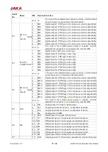
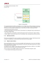
Figure 5-10 Digital output
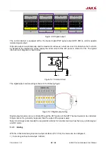
The control cabinet is equipped with a 16-channel digital PNP signal output (DO1-DO16), which supports
isolated signal output.
High-side output is used internally, and the maximum continuous current can reach 1A. But when the V+ shorts
by default to the internal 24V power supply, the total current of the 24V power is limited to 1.5A. The typical
internal circuit diagram is shown below:
Figure 5-11 Internal circuit
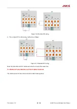
The digital output module wiring is shown in the following figure:
Figure 5-12 Digital output wiring
Digital output module can be controlled through the DO function of the APP. The load needs to be controlled.
Single channel 1A, generally no greater than the output of the power supply.
Note: It is strongly recommended to use protective diodes for inductive load (such as the relay, electromagnet,
and DC motor).
5.3.5
Analog
With the 2-channel analog input and output interfaces (Ch1, Ch2), the mode can be configured:
1)
Current signal input and output: 0-20mA;
1
2 3 4 5 6 7 8
DI(1~8)
V+
1
2 3 4 5 6 7 8
DO(1~8)
V-
9 10 11 12 13 14 15 16
DI(9~16)
V+
9 10 11 12 13 14 15 16
DO(9~16)
V-
P1
P2
P3
P4
Vz
V-
V-
V+
DOx


