File Version: 3.2
39
/
62
JAKA C Series Hardware User Manual
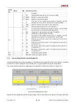
output is stopped when overloading, the recommended output is less than or equal to 1A). If the user needs a
larger power output, it can power the V+ power supply with external “power”, which supports a maximum current
of 1.2A per channel. When using the external 24V power supply, you need to unplug the P8 interface 0V and
24V default jumper. 24V is the internal power , and 0V is the internal GND. V+ is the positive electrode
of all universal digital I/O interfaces, and V- is the negative for all general digital I/O interfaces. The default
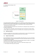
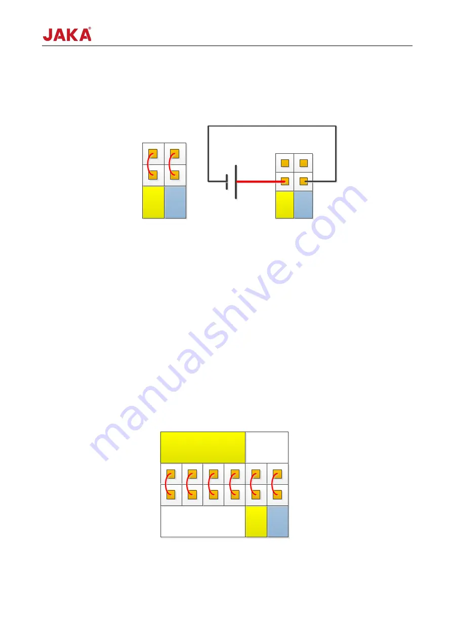
configuration is the connection to the internal power supply. See Figure 5-3:
Connect internal power
Connect external power
Figure 5-3 Power wiring
5.3.2
Safety I/O Interface
To ensure the safety function configuration of the robot, the control cabinet provides two fixed safety function
input interfaces, user can configure the interfaces for emergency stop and protective stop of the robot. EI and
SI stand for emergency stop and protective stop respectively, and they both have 2-channel redundant design.
When any signal is valid, this function can be enabled. Both emergency stop and protective stop are 2-channel
design. If you need to use external safety I/O devices, please select the device that supports dual-channel
design.
Users can access security doors, security light curtains, sensors, etc., according to actual safety requirements.
1. Default safety configuration
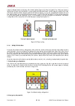
The robot can be operated without any additional security equipment. The EI1-2 and SI1-2 is short connected
to the V+, while the V+ shorts to 24V, and the V- shorts to 0V, indicating that the 24V power supply is internally
provided by the control cabinet, as shown in Figure 5-4:
Figure 5-4 Default safety configuration
2. Emergency stop switch
V+ V-
24V
0V
P8
接内部电源
V+ V-
24V
0V
P8
接外部电源
+
-
24V
0V
P8
默认出厂安全配置
EI
1
2
SI
1
2
V+
V+ V-
0V
24V
P8


