If you find that the GridBee has quit operating, the
following checks can be performed by a qualified
person such as an electrician:
Checks -
1) Verify that there is power available to the
control box and the On/Off switch is in the On
Position.
2) Confirm that the motor circuit fuse (4 Amps) is
not blown.
3) Follow each cord from the external electronic
controller to its originating component and be sure
it is not damaged or compromised.
OPTIONAL Visual Electronic Controller Check
- The GridBee contains an LED (Light Emitting
Diode) blink sequence that indicates the machine
operation status. The blinking LEDs are found
on the Brain-board located inside the control box.
Normal GF10000PW operation will include a 4X
Red Blink Code.
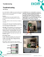
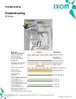
DC Voltage Check -
If a DC voltmeter is available, the motor circuit
voltage can be measured off terminal blocks
1 and 2. The proper motor voltage should be
approximately 45vDC
Brain Board voltage should be approximately
12vDC and can be measure as shown to the right.
Ixom Watercare, Inc. is committed to serving our
customers. Feel free to contact a Ixom Watercare,
Inc. Customer Service Representative if you
experience any problems with your GridBee. At
Ixom Watercare, Inc., we will get you technical
support, parts, or a service visit to make sure that
your GridBee is back online in short time.
(866) 437-8076 or [email protected]
12 VDC+
12 VDC-
4 Amp
Fuse
45 VDC SUPPLY TO
GRIDBEE UNIT
+ 45 VDC (White)
- 45 VDC (Black)
MOTOR (Red)
MOTOR SIGNAL - (Green)
BRAINBOARD TO
MOTOR CONTROL
COMMUNICATIONS
1
2
3
4
7
8
9
AC LINE (Black)
AC NEUTRAL (White)
AC GROUND (Green)
AC GRID POWER
BRA
M
CO
©2022 IXOM Watercare Inc. | www.ixomwatercare.com | 866 - 437 - 8076 | [email protected]
Troubleshooting
Troubleshooting
GF Series
10300_20220121
O&M_GF2500_10115_20220121 - 32

