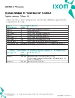
Description of Holding Registers in Order of Importance
(Memory Table starts at zero, 0)
Register
Address
(Base 10)
Status Item
Description
0
NA
Not Applicable
1
NA
Not Applicable
2
NA
Not Applicable
3
NA
Not Applicable
4
Current
Epoch High
This is the date and time data for the GridBee. The format is the same as that
of the “Unix epoch”, (Epoch High * 65536 + Epoch Low),
where the value is the
number of seconds since 00:00:00 UTC on January 1, 1970. This value is set
by the GPS hardware in the GridBee controller.
Querying register 5 and testing the response against the previous value is a
good way to monitor the communication link between the modbus master and
the slave GridBee controller.
5
Current
Epoch Low
6
NA
Not Applicable
7
NA
Not Applicable
8
NA
Not Applicable
9
Visual Status
Indicator
This value gives an indication of the GridBee controller health blink indicator.
During normal operation the following values will appear:
4 = (4 Blink Red = Healthy Operation)
Any other indication requires attention:
3 = (3 Blink Red = Motor Controller Communication Error)
10
Motor Speed
The unit for this value is RPM in hundredths. To obtain RPM, divide the value
by 100.
11
Motor Direction
The value of 0 indicates that the motor will be stopped, the value of 1
represents movement in the forward direction, whereas the value of 3 indicates
reverse movement. Viewed from behind or above the motor clockwise motion
is “forward”.
12
Motor Current
The unit for this value is milliamps.
©2022 IXOM Watercare Inc. | www.ixomwatercare.com | 866 - 437 - 8076 | [email protected]
Technical Data Sheet
GridBee GF Series SCADA Output
1657_10362_20220110
O&M_GF2500_10115_20220121 - 40

