background image

2 - 49

K2    Sprint

SN No.


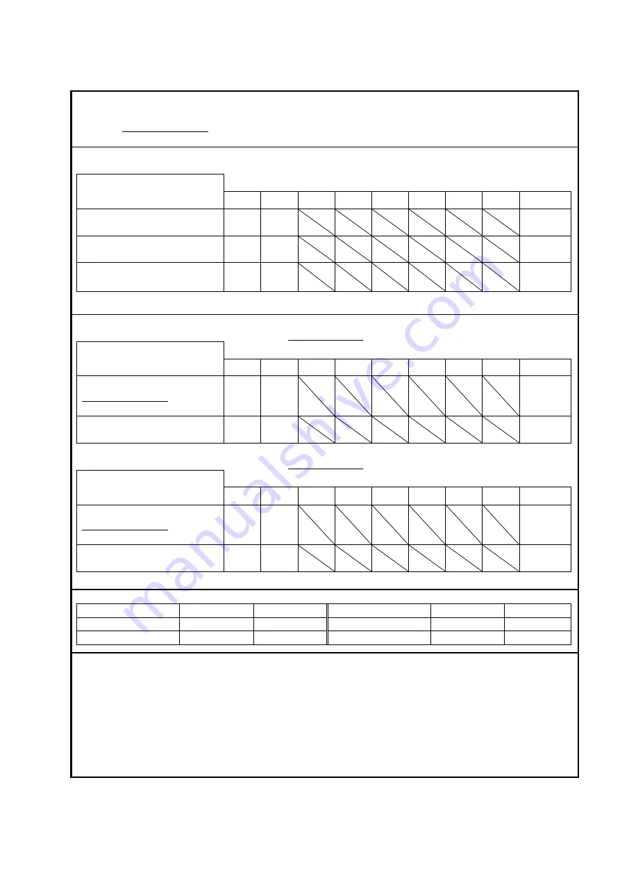
Voltage input sensitivity test / monitoring output test
Input sensitivity : 5mV/(m/s

2

) / Input type : Voltage input (AC)

Item

Criterion

Ch.1

Ch.2

Ch.3

Ch.4

Ch.5

Ch.6

Ch.7

Ch.8

Result

Input volage (mVrms)

353.5

Measured 

value

Acceleration (m/s

2

)

98.00 ~ 102.00 (100±2%)

OK / NG

Monitor output (mVrms)
335.825

371.175(

353.5±5%

)

OK / NG

Charge input sensitivity
Input sensitivity : 5pC/(m/s

2

) / Capacitor : C:                            (pF) / Input : charge input (1mV/pC)

Item

Criterion

Ch.1

Ch.2

Ch.3

Ch.4

Ch.5

Ch.6

Ch.7

Ch.8

Result

Input voltage (mVrms) :
                             
1000/C×353.5 (mVrms)

Measured 

value

Acceleration (m/s

2

)

98.00 ~ 102.00 (100±2%)

OK / NG

Input sensitivity : 5pC/(m/s

2

) / Capacitor : C:                            (pF) / Input : charge input (10mV/pC)

Item

Criterion

Ch.1

Ch.2

Ch.3

Ch.4

Ch.5

Ch.6

Ch.7

Ch.8

Result

Input voltage (mVrms) :
                             
1000/C×353.5 (mVrms)

Measured 

value

Acceleration (m/s

2

)

98.00 ~ 102.00 (100±2%)

OK / NG

Measurement instruments

Name

Model

Serial No.

Name

Model

Serial No.

Voltmeter
Capacitor (1000pF)

Remarks :

Содержание K2-CE

Страница 1: ...Vibration Control System K2 CE K2Sprint CE Common Part TYPE II Instruction Manual IMV CORPORATION...

Страница 2: ...Manual System Applied K2 K2Sprint Application Software later than Version 14 4 0 Device Driver later than Version 11 1 0 Note If the hardware used is the old type system its specifications conform to...

Страница 3: ...rints 13 3 0 2017 03 01 Correction of misprints 13 6 0 2017 10 02 Additional description of Viewer function to restore the display configuration overlaid graph file selection method additional descrip...

Страница 4: ......

Страница 5: ...Up and Maintenance 2 1 2 1 Installation 2 1 2 1 1 Environment for Installation 2 1 2 1 2 Installation of K2 Interface Board 2 1 2 1 3 Connection to PC 2 2 2 1 4 Connection to Excitation System 2 2 2...

Страница 6: ...1 Excitation System Information name 3 2 3 3 2 Drive Output 3 2 3 3 3 Polarity 3 2 3 3 4 Initial Output Voltage Default Value 3 3 3 3 5 Rating Information 3 3 3 3 5 1 Load from system model 3 3 3 3 6...

Страница 7: ...e change 4 27 4 3 4 Cursor Display 4 28 4 3 4 1 Double cursor display 4 29 4 3 4 2 Peak search 4 30 4 3 4 3 Registration of cursor data 4 31 4 3 4 4 Cursor display in 3D graph 4 33 4 3 5 Graph Change...

Страница 8: ...ick Report 4 84 4 10 Waiting for Stabilization of IEPE Sensor 4 87 4 11 Customizing Toolbar Buttons 4 88 Chapter 5 Energy saving operation ECO option ISM 5 1 5 1 Outline 5 1 5 2 Constraints in operati...

Страница 9: ...ify the sensitivity of input environment information 7 24 7 3 3 Supplementary Explanation of Test Files Mode 7 25 7 3 3 1 Folder 7 25 7 3 3 1 1 Contents Displayed on Screen 7 25 7 3 3 1 2 Test summary...

Страница 10: ...Chapter 9 Intended Use Judgment Function 9 1 9 1 Outline 9 1 9 2 Operation Example 9 2 9 2 1 Procedures 9 2 Chapter 10 Test Record 10 1 10 1 Outline 10 1 10 2 Operation Example 10 2 10 2 1 Startup 10...

Страница 11: ...ctions that you must observe to ensure safe and proper handling of the vibration control system Before using this system please read this instruction manual carefully to understand the contents thorou...

Страница 12: ...e understand the following description and observe the instructions without fail Improper handling of this system may result in injury or property damage General cautions It is prohibited that the sys...

Страница 13: ...dy and life and property damage instructions for each unit are indicated on the labels The indications and meanings of the labels are described below Before operating this system be sure to understand...

Страница 14: ...ontrol Signal Input Do not apply a voltage higher than the specified voltage to the terminals Refer to 1 5 Hardware Specifications Caution label External Input Do not apply a voltage higher than the s...

Страница 15: ...label Control Signal Input Do not apply a voltage higher than the specified voltage to the terminals Refer to 1 5 Hardware Specifications Caution label External Input Do not apply a voltage higher tha...

Страница 16: ...nstallation One USB port necessary for protect device For Eco shaker Net Framework 4 6 1 has been installed operation is not guaranteed with any other than this version One Built in RS 232C port 9 pin...

Страница 17: ...9ft cable K2ST 34 011 x 1 Multiple cabinets are necessary when the input channels are increased In this case each cabinet is connected by using the cabinets K2ST 11 011 appearance diagram K2 Front K2...

Страница 18: ...Unit is a hardware bundle in which the dedicated hardware having only two input output channels and PC I F Kit are packaged No channel can be added in K2Sprint I O Unit appearance diagram K2 Sprint F...

Страница 19: ...60664 1 8 Pollution Degree 2 according to IEC60664 1 9 European Directive Low Voltage Directive 2014 35 EU EMC Directive 2014 30 EU 10 Number of slots 3 possible to increase by connecting cabinets 11...

Страница 20: ...llution Degree 2 according to IEC60664 1 9 European Directive Low Voltage Directive 2014 35 EU EMC Directive 2014 30 EU 10 Number of slots 1 impossible to increase 11 Number of Input Output Channels e...

Страница 21: ...of Acquisition unit conversion Input format Max input acquisition unit Charge 1 0 mV pC 10000 A Charge 10 mV pC 1000 A Voltage input 10000 A IEPE input 10000 A A Sensor sensitivity mV acquisition unit...

Страница 22: ...nnels is used as drive output 2 Output Terminal BNC 3 Output Format Voltage 4 Maximum Output 10 000 mV 5 Sampling Frequency Maximum 51 2 kHz 6 D A Converter Method method Resolution 24 bit Dynamic ran...

Страница 23: ...5 4 3 2 1 STOP O8A O7A O6A O5A O4A O3A O2A O1A O8B O7B O6B O5B O4B O3B O2B O1B I8 I7 I6 I5 I4 I3 I2 I1 STOP O8A O7A O6A O5A O4A O3A O2A O1A O8B O7B O6B O5B O4B O3B O2B O1B I8 I7 I6 I5 I4 I3 I2 I1 50 4...

Страница 24: ...ins are used as Emergency Stop Input Contacts The function of the drive output stop is realized by using the mute function of D A converter and reduce the drive output with taking the time of 1024 sam...

Страница 25: ...ble on the software IEPE input supports the TEDS function Monitor Output Terminals are provided for every input channel Output Analogue signal output including the excitation control drive signal for...

Страница 26: ...ected by relay device 3 K2Sprint Cabinet K2SP 11 011 Input Analogue signal acquisition for 2 Simultaneous Sampling Input Channels is available 24 bit D A converter of method is used The input formats...

Страница 27: ...ion for K2 The PC and K2 I O Unit are available to connect by using a dedicated cable This board has the functions as below Generation of Sampling Clock Real time waveform data sending receiving by DM...

Страница 28: ...fied by PSD and sinusoidal wave given as data of frequency and excitation level This software is an optional function which runs on RANDOM 4 ROR Random On Random Software for excitation test system on...

Страница 29: ...e set on side panel Please do not disturb the cooling air by putting things around the machine Avoid direct sunlight Set the system in fresh air Refer to Chapter 1 System Configuration about the detai...

Страница 30: ...ACE 2 1 4 Connection to Excitation System Input Signal cables of each pickup set to the shaker are connected to input terminals of front panel of the machine Please pay attention not to mistake the co...

Страница 31: ...ystem 3 Do not use the visual effects that load the computer e g settings below Disable Enable desktop composition Disable Display window content during dragging Disable Enable transparency 4 Windows...

Страница 32: ...ecuted 2 License installer Information of the license you purchased can be installed 3 Manual installer The operation instruction in PDF format can be installed Always install them in the following or...

Страница 33: ...2 5 2 2 1 Installation of License Procedures Step 1 Double click the icon of LicenseSetup exe in the license installer folder Press the button of Yes if the screen of User Account Control appears...

Страница 34: ...2 6 Step 2 The initial screen of installation appears Press the button of Next...

Страница 35: ...2 7 Step 3 The screen of starting installation appears Press the button of Install Then installation of the license information is started...

Страница 36: ...2 8 Step 4 After the installation is completed the screen noticing the completion of installation appears Press the button of Finish Then installation of license information is complete...

Страница 37: ...2 9 2 2 2 Installation of Application Procedures Step 1 Double click the icon of Setup cmd in the application installer folder Press the button of Yes if the screen of User Account Control appears...

Страница 38: ...2 10 Step 2 The initial screen of installation appears Press the button of Next...

Страница 39: ...ems shown in the list are as follows Select all the items normally K2 Software The K2 application can be installed K2 Driver The K2 interface board device driver can be installed Protect device Driver...

Страница 40: ...f starting installation appears Press the button of Install Installation of the K2 application is started After the installation of the K2 application is finished the shortcut icon of K2Launcher is ma...

Страница 41: ...2 13 Step 5 After the installation of the K2 application is finished the screen noticing the installation of the K2 interface board device driver appears Press the button of Next...

Страница 42: ...2 14 Step 6 The screen of starting the installation of the device driver appears Press the button of Next Installation of the device driver is started...

Страница 43: ...ress the button of Install Unless the box of Always trust software IMV CORPORATION is checked the screen confirming installation appears for three times If the box of Always trust software IMV CORPORA...

Страница 44: ...2 16 Step 8 The screen of finishing the device driver installation appears Press the button of Finish...

Страница 45: ...oard is finished screen of starting the installation of the device driver of protect device appears Press the button of Next Step 10 After installation of the protect device driver is finished the scr...

Страница 46: ...2 18 Step 11 The screen of starting the setting of PC for the use of K2 appears Press the button of Next Then the PC setting process is started...

Страница 47: ...y computer now and press the button of Finish Then the PC is restarted After the PC completed its restart installation of the application is completed If the protect device is inserted into the PC the...

Страница 48: ...2 20 2 2 3 Installation of Manual Procedures Step 1 Double click the icon of ManualSetup exe in the manual installer folder Press the button of Yes if the screen of User Account Control appears...

Страница 49: ...2 21 Step 2 The initial screen of installation appears Press the button of Next...

Страница 50: ...2 22 Step 3 The screen of selecting the language of manual appears Select your desired language and press the button of Next...

Страница 51: ...2 23 Step 4 The screen of starting installation appears Press the button of Install Then installation of the manual is started...

Страница 52: ...completion of installation appears Press the button of Finish Then installation of the manual is complete When the installation is completed the folder of Manual appears on the Desk top screen Double...

Страница 53: ...cribes the uninstallation of the K2 software 2 3 1 Uninstall or change a program Access to the screen displaying the message of Uninstall or change a program through the Control Panel 1 Windows 7 Proc...

Страница 54: ...ol Panel screen appears If the viewing method of the control panel is set to Large icons or Small icons select Programs and Features If the viewing method of the control panel is set to Category selec...

Страница 55: ...2 27 Step 3 The screen displaying the message of Uninstall or change a program appears...

Страница 56: ...2 28 2 Windows 10 Procedures Step 1 Right click the Start Menu And select Control Panel on the displayed menu...

Страница 57: ...ol Panel screen appears If the viewing method of the control panel is set to Large icons or Small icons select Programs and Features If the viewing method of the control panel is set to Category selec...

Страница 58: ...2 30 Step 3 The screen displaying the message of Uninstall or change a program appears...

Страница 59: ...dures Step 1 Select K2 License on the screen of Uninstall or change a program and then select Uninstall Step 2 The message box asking the confirmation of uninstallation appears Press the button of Yes...

Страница 60: ...2 32 Step 3 After the uninstallation of license is completed the screen noticing the completion of uninstallation appears Press the button of Finish Then uninstallation of license is complete...

Страница 61: ...Procedures Step 1 Select K2 on the screen of Uninstall or change a program then select Uninstall Step 2 The message box asking the confirmation of uninstallation appears Press the button of Yes Then...

Страница 62: ...omplete the screen noticing the completion of uninstallation appears Select Yes I want to restart my computer now and press the button of Finish Then the PC is restarted After the restart of the PC is...

Страница 63: ...Procedures Step 1 Select K2 Manual on the screen of Uninstall or change a program and then select Uninstall Step 2 The message box asking the confirmation of uninstallation appears Press the button of...

Страница 64: ...2 36 Step 3 After the uninstallation is completed the screen noticing the completion of uninstallation appears Press the button of Finish Then uninstallation of manual is complete...

Страница 65: ...stall a new version software This procedure is common to the upgrading of all the Application license and manual For operating procedures of the uninstallation of software refer to 2 3 Uninstallation...

Страница 66: ...ware This function can be set to ON OFF and the setting of Contact Polarity in Emergency Stop operation is also available on the hardware Set the contacts using the switches within the cabinet Be sure...

Страница 67: ...K2ST 23 011 Input Module K2ST 23 012 Note that the followings to set up the ID of each module Not to set the modules having the same IDs on a system Set less than 200 value to the module ID Set the I...

Страница 68: ...the power supply to the K2 I O Unit turn on the power supply to the power amplifier Step 3 Start up the application For the procedures of application startup refer to 4 2 1 Application Start Up in Cha...

Страница 69: ...r an authorized dealer of your purchased system When you contact us enter necessary items in the contact form that comes with the system and give us information on your request as detailed as possible...

Страница 70: ...ng a blank module panel to the I O unit slot and the interface board to the PC All of these fixing screws must be tighten 6 Performance Check Check the item in 2 7 3 1 2 7 3 1 Performance Check Perfor...

Страница 71: ...the mode of the voltmeter to AC voltage measurement 4 Start the operation by K2 5 Next set the indicated value of the voltmeter to 353 5mV 0 5mV by adjusting the drive voltage of K2 Record the value o...

Страница 72: ...ded to be measured and recorded Charge input sensitivity test Connection of the instruments Connect the equipment by the cables as in the same way as in the system of Voltage input sensitivity test mo...

Страница 73: ...measured data 9 These procedures are needed to be operated also for Ch 3 and Ch 4 When the optional input channels are added the input channels Ch1 Ch8 of the expansion board are also needed to be me...

Страница 74: ...is item done Yes No 2 Fan Correctly running Yes No 3 Contact cleaning Is this item done Yes No 4 Instruction manual Available as needed Yes No Yearly Inspection Maintenance item Judgment criteria Resu...

Страница 75: ...335 825 371 175 353 5 5 OK NG Charge input sensitivity Input sensitivity 5pC m s2 Capacitor C pF Input charge input 1mV pC Item Criterion Ch 1 Ch 2 Ch 3 Ch 4 Ch 5 Ch 6 Ch 7 Ch 8 Result Input voltage m...

Страница 76: ...rge input sensitivity Input sensitivity 5pC m s2 Capacitor C pF Input charge input 1mV pC Item Criterion Ch 1 Ch 2 Ch 3 Ch 4 Ch 5 Ch 6 Ch 7 Ch 8 Result Input voltage mVrms 1000 C 353 5 mVrms Measured...

Страница 77: ...put sensitivity 5pC m s2 Capacitor C pF Input charge input 1mV pC Item Criterion Ch 1 Ch 2 Ch 3 Ch 4 Ch 5 Ch 6 Ch 7 Ch 8 Result Input voltage mVrms 1000 C 353 5 mVrms Measured value Acceleration m s2...

Страница 78: ...ems shall be out of the scope of our liability even within the warranty period 1 An accident attributable to the user s appurtenant work for this system fall down power supply grounding etc 2 An accid...

Страница 79: ...mv tec com IMV EUROPE LIMITED German Sales Office Landsberger Str 406 D 81241 Munich Germany TEL 49 0 89 21 545 9900 IMV THAILAND CO LTD Amata City Chonburi Industrial Estate Phase 9 700 907 Moo 5 Tam...

Страница 80: ...No Contents of request If you order repair service specify the name and model of the product to be repaired and trouble conditions After receipt of your request by E mail IMV will contact you Please u...

Страница 81: ......

Страница 82: ......

Страница 83: ...on on the right of the list of I O Module Configuration when the K2 I O Unit Configuration is changed Before renewing the information I O Unit should be connected to the current PC by the dedicated ca...

Страница 84: ...e registration appears 3 3 1 Excitation System Information name 1 Meaning This item is for inputting of the registration name of the excitation system shaker amplifier to be used 3 3 2 Drive Output 1...

Страница 85: ...eaning The system rating information is set automatically by selecting a model from the list of excitation systems provided 3 3 6 Control Frequency Range is limited 1 Meaning This item is for setting...

Страница 86: ...3 4 3 3 9 Armature mass 1 Meaning This item is for setting of the armature mass of the shaker The armature mass is used for the excitation force check in the application software such as SINE...

Страница 87: ...file creation Add A new input channel is added Change Defined content of a selected input channel is changed Delete A selected input channel is deleted from the registration list The registered order...

Страница 88: ...harge Input is selected when the acceleration pickup output of charge output type is directly connected to the I O Module or Input Module I O Module and Input Module are available to select both of ga...

Страница 89: ...nput channel is treated as a signal having the negative polarity That is the data obtained after A D converting multiplied 1 The default value of this item is set to Positive 3 4 8 TEDS Access 1 Meani...

Страница 90: ...f available commands appears by clicking each name of menus Each tool bar displays the commands that are frequently used in the menu as icons When an icon is clicked the command corresponding with thi...

Страница 91: ...Operation 4 2 1 Application Start Up Procedures Step 1 Double click the K2Launcher on the desk top screen Step 2 The K2 Launcher is started Select the icon of the application to be started and press...

Страница 92: ...4 3 4 2 2 Exit from Application 1 K2 Launcher Press the button Close on the screen...

Страница 93: ...using the command in the menu bar Procedure of closing by Close Button The application is ended by clicking the close button on the upper corner of the right in the window in Test Definition mode Proc...

Страница 94: ...ows This command is for creating a new test Test Definition Test Condition Test Contents is newly defined This commend is for generating a new test in simplified definition mode The contents of defini...

Страница 95: ...FR function is to be measured Drive Generation Drive waveform data is generated from the reference data and Inverse XFR function Waiting for Excitation Start Excitationnoperation is to be started When...

Страница 96: ...ata Available only in CAPTURE Calculation between numeral values is operated to the waveform data Available only in CAPTURE Edging process that makes the beginning and the ending point of waveform dat...

Страница 97: ...bed as below 4 2 4 1 File Open The dialog shown as below appears by the following procedures Select File in the menu bar and click Open or click the icon of Open in the tool bar Select a file type and...

Страница 98: ...ar and click Save as or operating the function of Save to save a new Test Definition File A comment can be inputted if it is necessary In the dialog box for processing files dedicated to this system C...

Страница 99: ...isplaying graphs and logs in a manner which is frequently used in scratchpad software like EXCEL Procedures Step 1 Select Window in the menu bar and click Add a Page Step 2 The picture as follows show...

Страница 100: ...4 11 Others Rename the page A name of the additional page can be changed by double clicking on the tab of the page in the display when it is necessary Name change window is displayed below...

Страница 101: ...g command is executed immediately Pallets are indicated split vertically Refer to 4 2 6 2 Moving the Palette Positions of displayed some pallets are changed by turning them counterclockwise Refer to 4...

Страница 102: ...4 13 4 2 6 2 Moving the Palette Palette can be moved by operating the palette operation button provided at the bottom of the displayed page Palette Palette...

Страница 103: ...7 1 Set Up In this clause set up method of both Test Definition mode and Test Operation mode is described The set up methods vary depending on each application Refer to the instruction manual of each...

Страница 104: ...ration is displayed 4 2 7 3 Manual Operation The control reference can be changed during the excitation by using manual operation box The set up methods vary depending on each application Refer to the...

Страница 105: ...display area leftward Moves in graph display area rightward Moves in graph display area upward Moves in graph display area downward Changes graph zooming by dragging Zooming horizontally only vertica...

Страница 106: ...by selecting the data from the data of Test Definition and Test Operation Procedures Step 1 Select Window in the menu bar and click Graph among the items Step 2 Select one item each in the list of Gr...

Страница 107: ...4 18 Step 3 A graph of the page displayed currently appears in the display...

Страница 108: ...explains how to display waterfall graphs For details of 3 Color map refer to Chapter 6 DATA VIEWER 1 Waterfall graph depth fixing Types of graphs applicable to this graph are as shown below SINE Monit...

Страница 109: ...Step 1 Proceed to Step 2 of the selection of graph to be displayed in the former section 4 3 2 Step 2 Select Waterfall graph from Graph type and press OK button For DATA VIEWER only Color map can be...

Страница 110: ...4 21 Step 3 Additional graph appears on the currently displayed page...

Страница 111: ...ded The following is the conditions for data addition SINE SOR When single sweep is completed RANDOM At loop renewal SHOCK When excitation is finished Notes Data before waterfall graph scroll display...

Страница 112: ...p 2 Select graph type and depth axis data and set up the maximum number of depth data If Monitor is selected as displayed data select your desired input channel After all the setup is complete press O...

Страница 113: ...4 24 Step 3 Additional graphs appear on the currently displayed page At this time data line is not drawn When the conditions for data addition described above are satisfied data is added sequentially...

Страница 114: ...4 25 4 3 3 Scale This function is for changing the scale of the graph displayed currently for its vertical and horizontal axes Procedures Step 1 Click a Scale change button on the graph display window...

Страница 115: ...4 26 Step 2 Change values of the graph range for horizontal axis displayed and press the OK button...

Страница 116: ...a can be set up Hidden line display Lines hidden backward hidden lines can be displayed Reverse direction display Data with large number can be placed foremost Ratio of horizontal axis The horizontal...

Страница 117: ...ed graph currently displayed Procedures Step 1 Right click the mouse button on the graph or click the cursor button to display the cursor in the graph Step 2 Use the dialog of Graph cursor The cursor...

Страница 118: ...edure Step 1 Check double cursor in the graph cursor dialog box Cursor 2 is enabled Step 2 Select and operate cursor 2 If cursor 1 is selected you can operate cursor 1 The graph cursor dialog box disp...

Страница 119: ...and move the cursor Searches the peak in the horizontal axis minus direction Searches the peak in the horizontal axis plus direction Min Searches the minimum value Max Searches the maximum value Condi...

Страница 120: ...ure Step 1 Press the Register button in the peak search setting window Step 2 The cursor data selected when the Register button has been pressed will be saved in the list Press the CSV File button to...

Страница 121: ...4 32 Step3 Press the Mark button to mark the cursor data displayed in the list...

Страница 122: ...4 33 4 3 4 4 Cursor display in 3D graph Although the operation procedures are similar to those of normal graph depth data needs to be selected...

Страница 123: ...graph displayed in the current display is changed Procedures Step 1 Click a Graph change button on the graph display window Step 2 Select one item each in the list of Graph type and another descripti...

Страница 124: ...rounds and valleys are marked with squares from the higher order The values appear in the legend window As for the peak detecting conditions maximum number of marks changing of display non display of...

Страница 125: ...the Graph color setting 4 3 7 1 Change Graph Color Select items to be changed on the tab of Graph color and change the settings of line types marks and colors Note The setting of Graph color setting i...

Страница 126: ...d test beginning time is displayed when excitation is started and test ending time is displayed when the excitation is ended This setting is valid for applications shown below SINE RANDOM SHOCK RESONA...

Страница 127: ...ed peaks and valleys are less than it only the detected items are marked Search in the scale range Whether peaks and valleys should be detected in the scale range currently displayed or in all the dat...

Страница 128: ...ition Graph and Log are printed out mainly by using the function of print executed by selecting File Print in the menu bar The items to be printed out are available to select by clicking on it Procedu...

Страница 129: ...the margin area If the number of characters displayed in header and footer are too large and they cannot be displayed completely In this case increase the height When Print per Graph is checked and tw...

Страница 130: ...f margin setting setting of footer header and date printing for the printer Procedures Step 1 Select File in the menu bar and click Printer setting among the items Step 2 Select the printer to be used...

Страница 131: ...press OK Header and footer are printed inside except the margin area If the number of characters displayed in header and footer are too large and they cannot be displayed completely In this case incr...

Страница 132: ...for setting of the graph display type of data line color and mark at printing Procedures Step 1 Select Option in the menu bar and click Graph setting among the items Step 2 Select Printer from Selecti...

Страница 133: ...4 44 Step 3 Select the data line and the color etc Then press OK to complete the setting Note Printer may not work correctly when the setting of Printer type is not set correctly...

Страница 134: ...5 File Conversion 4 5 1 File conversion to CSV This function is for converting a data file of K2 file format to that of CSV file format Procedures Step 1 Click a Save Data button on the graph display...

Страница 135: ...lerance 1st column 2nd column 1st line Frequency Hz Response unit Reference uni Abort upper limi uni 2nd line Fixed characters are written in Italic Data name of graph is substituted for a data name U...

Страница 136: ...d for a unit Frequency data is substituted in the 1st column Spectrum data is substituted from the 2nd column Conversion of SHOCK Waveform Data Fixed characters are written in Italic Data name of grap...

Страница 137: ...soft Excel software installed Note This program supports only for Microsoft Excel 2010 Microsoft Excel 2013 Microsoft Excel 2016 and Microsoft Excel 2019 Procedures Step 1 Select a graph to be convert...

Страница 138: ...ched Japanese English Chinese Russian or German can be selected as of October 29 2015 Response statuses of respective K2 applications are varied Operating procedure Step 1 Select Option from the menu...

Страница 139: ...hat is a data necessary for the test is to be recorded by saving its Test Definition file of the state at excitation completed Press the icon of Save in the state at excitation completed A dialog box...

Страница 140: ...a Test Definition file Merit The state at the test completion is to be checked again after the test completion Excitation operation is to be restarted from the state at excitation completed Demerit Te...

Страница 141: ...4 52 Step 2 Press Yes when a dialog of message for assuring appears...

Страница 142: ...ation system information registered in Test Definition file to another Procedures Step 1 Select File in the menu bar and click Another excitation system information loading among the items Step 2 Sele...

Страница 143: ...4 54 Step 3 The corrected server name and Excitation system information name are displayed Press Save to overwrite the Test Definition file...

Страница 144: ...an input channel is also available during the test definition 4 7 5 New Input Environment Information Loading Input channel information is available to load newly from the input channel information r...

Страница 145: ...ed in Test Definition is available to be registered in Environment setting as Input channel information Procedures Step 1 Select File in the menu bar and click New Input environment information saving...

Страница 146: ...the 50 pin connectors arranged on the backside panel of I O Unit Configuration of pin connectors is described as below Input terminal 8 bits Output terminal 8 bits are available Additionally terminal...

Страница 147: ...always connected in a combined test You don t have to define the contact I O information every time at generating a test when you use the function described in this clause Procedures Step 1 Select Opt...

Страница 148: ...4 59 Step 3 Press the Define button of Contact I O information Step 4 Operate the setting of Contact I O and press OK...

Страница 149: ...4 60 Step 5 Press the OK button...

Страница 150: ...lt no order PAUSE This item is for pausing of the excitation at closed And this item is for canceling the paused state and continuing the excitation at opened Valid the state in operation Default no o...

Страница 151: ...xcitation finished Default no order Available software SHOCK AUXIN1 This item is valid only when the application program defines signal specification SINE Sweep reverse valid only in Sweep Test RANDOM...

Страница 152: ...signal must be a pulse keeping up more than about 500ms Excitation level is increased decreased for the level specified in the application program by a single pulse Pulses can be outputted continuousl...

Страница 153: ...MEUP Test operation is completed when the specified test time is passed Finished normally FINISHED The system is in the state of excitation completion Including abort ABORTED The excitation is stopped...

Страница 154: ...1 the same as in the above AUXOUT12 Auxiliary output 12 the same as in the above AUXOUT13 Auxiliary output 13 the same as in the above AUXOUT14 Auxiliary output 14 the same as in the above AUXOUT15 Au...

Страница 155: ...ditional client option is necessary to operate the remote control that is used to execute other operations such as Test Stop or Test Start from a distant place LAN environment is required to use this...

Страница 156: ...cally on the PC for monitoring check the check box of Add the auto updating function to HTML and specify the value of Auto updating interval When Add the auto updating function to HTML is not checked...

Страница 157: ...g in test operation HTML file generated by the K2 is opened by using a browser in the PC on the LAN The example display as below is in the case of using Microsoft Internet Explorer HTML file generated...

Страница 158: ...tion However the excitation had stopped after 5 minutes from the excitation start because the pickup happened to be dislocated Such an accident in operation can be acknowledged by E Mail Sending Funct...

Страница 159: ...4 70 Step2 Check the check box of Assert E mail sending function sending a e mail And set the necessary items In initial setting the outgoing mail server setting window automatically opens...

Страница 160: ...4 71 Step3 Set the outgoing mail server Please ask to the administrator of Net Work about the setting of sending mails if it is necessary...

Страница 161: ...is for specifying the mail address of the sender Specify an E Mail address to send the E Mail E Mail is sent to the addresses registered in this list from the K2 However note that E Mail may not be s...

Страница 162: ...hs can be used by linking with Bookmarks of Microsoft Word The numeral values the letters and the graphs specified as Bookmarks can be attached to the report automatically when these Bookmarks are des...

Страница 163: ...le of Microsoft Word to be used or to make correspondence of the Output Items with Bookmarks newly Go to Step 3 B Select the registration name in Select by registered name to use the Output Items corr...

Страница 164: ...ist of Output Item name Press the Change button in Correspondence Definition Available Output Items vary in each applications as SINE RANDOM Graph Data The graphs displayed at generating reports are t...

Страница 165: ...e if it is necessary A Press the Common output items button to change the setting of Common Output Items Go to Step 5 B Specify a registration name in Select by the registeration name to use the Commo...

Страница 166: ...tached to the Bookmarks corresponded with The characters and the numeral values are set to the Output Item to be needed Specify a registration name of Common Item set to register the set Common Output...

Страница 167: ...finition Registration to register the set Correspondence And press the Name change button When the set Correspondence Item is registered in this item it can be selected in Select by registered name at...

Страница 168: ...is done if it is necessary A Press the Setting button to change the setting of Common Output Items Go to Step 8 B Specify a registration name in Select by the registeration name to use the Common Outp...

Страница 169: ...hed to the Bookmarks corresponded with The characters and the numeral values are set to the Output Item to be needed Specify a registration name of Common Item Set to register the set Common Output It...

Страница 170: ...4 81 Step 9 Press OK after completing of the necessary settings...

Страница 171: ...n is pressed a WORD file according to the setting of Report Generator is generated automatically The graphs displayed at pressing the Report generation button are treated as the objective for Graph of...

Страница 172: ...4 83 Report of testing result generated by Report Generator...

Страница 173: ...Generator and non necessity of Microsoft Word On the other hand it does not allow fine position adjustment Use the functions appropriately for your purpose If you choose Microsoft Word as the destina...

Страница 174: ...pplication Click Output button To add a logo input or select the path to the target image file Either PNG raster type or EMF vector type graphic image type can be selected In the EMF images do not get...

Страница 175: ...ion of quick report with button operation When a test is finished press Quick button When the Quick button is pressed a quick report is generated through the display software Items to be output are th...

Страница 176: ...the waiting for excitation start status When the stop button is pressed while the screen of Waiting for stabilization of IEPE is displayed the operation mode is switched to the waiting for excitation...

Страница 177: ...lows change in the order of toolbar buttons shown on the display of K2 application and choice between display and non display of toolbar buttons and addition of separators Procedures Step1 Select Opti...

Страница 178: ...nged select the button first and move the cursor with upward or downward arrow button If any separator needs to be inserted select the button just above it and press Separator button To return to the...

Страница 179: ...ECO SHAKER operation All the K2 application software in the ECO SHAKER system must be installed with the ECO option mixture of the ECO option attached applications and not attached ones is not allowed...

Страница 180: ...no constraints in operation But a part of E save functionality or whole functionality becomes invalid Air cooled systems Blower control only Water cooled systems E save functionality is invalid 5 2 2...

Страница 181: ...alidated Excitation level up Excitation level down Excitation level change ROR Narrow band Random ON OFF Shift to the beginning of the next sweep Sweep reverse Sweep hold Sweep hold cancel 1 If the in...

Страница 182: ...K2 application installed on the system Notice If the setting items described here is changed incorrectly the ECO SHAKER system would not work correctly Please do not change the settings from those se...

Страница 183: ...equired not only to select No but also to modify the hardware Returns the settings to the default ones Set K2 and ISM communication log saving Select the K2 and ISM IDs for communication Select the na...

Страница 184: ...5 6 5 4 1 Initial setting factory setting Factory setting is as shown below To restore it click Initialization...

Страница 185: ...with the application software 2 2 Available functions with DATA VIEWER 1 Available functions in graph operation with the application software 2 Print function 3 Report generation function using Report...

Страница 186: ...h axis data type File name Time 4 Elapsed time SINE RANDOM only 4 Sweep count SINE only 4 Loop count SHOCK only 4 5 Number of graphs displayable simultaneously 255 6 Unavailable function Report genera...

Страница 187: ...aph window This command is for displaying new overlaid graphs and adding a new graph window Print Print preview Report generation on Microsoft Word Report Generator This command is for displaying new...

Страница 188: ...6 4 This command adds test definition to the graph window page being selected This command adds history log to the graph window page being selected...

Страница 189: ...6 5 6 2 2 Display of Standard Graph Procedure Step 1 Press the Open button Step 2 Select the graph data file...

Страница 190: ...graph to be displayed As for the graph type applicable to 3D graph Waterfall graph or Color map can be selected For details refer to 4 3 2 1 Selecting of 3D graph Step 4 A graph window is added and th...

Страница 191: ...lowing overlaying differs depending on the screens 6 2 3 1 Select on Tree Display Procedure Step 1 Press the Overlaid graph button Step 2 Overlaid graph selection dialog is displayed All graph data fi...

Страница 192: ...e display conditions Step 4 The selected graphs are set to be subject to overlay operation Only graphs with the same graph type and physical quantity can be overlaid The files with check are overlaid...

Страница 193: ...set up of graphs to be overlaid and then press the OK button Step 6 A graph window is added and the selected graphs are overlaid and displayed Those graphs can be operated in the same way as those on...

Страница 194: ...e button so that the graph is deleted from the list in the field and removed from the group of the graphs to be overlaid 3 To display the different type of graphs delete all graphs which are set up an...

Страница 195: ...6 11 6 2 3 2 Select on Dialogue Display Procedure Step 1 Press the Overlaid graph button Step 2 Overlaid graph data selection dialogue appears Press Add button...

Страница 196: ...6 12 Step 3 Select desired data file Some files can be selected at a time...

Страница 197: ...If the data type is set to Monitor select the monitor channel If data files different from the selected application type are displayed they are displayed in gray Checked items are to be displayed Data...

Страница 198: ...6 14 Step 5 Graph window is added and the selected graph appears Change of displayed graph Press the graph change button...

Страница 199: ...aphs are excluded from Overlaid graph targets 2 Select desired graphs and press the Delete button Then they are deleted from the Overlaid graph display area and Overlaid graph targets Overlaid graph d...

Страница 200: ...6 16 6 2 4 Display of 3D graph Procedure Step 1 Press 3D graph button Step 2 3D graph data selection dialogue appears Press Add button...

Страница 201: ...6 17 Step 3 Select desired data file Some files can be selected at a time...

Страница 202: ...data type If the data type is set to Monitor select the monitor channel If data files different from the selected application type are displayed they are displayed in gray Data files whose types are...

Страница 203: ...6 19 Step 5 Graph window is added and the selected graph appears Display example of waterfall graph Display example of color map...

Страница 204: ...he graph change button 3D graph data selection dialogue appears Addition or deletion of desired graph is allowed 3D graph display area Unchecked items are not the objects of 3D graph Deletes from 3D g...

Страница 205: ...tion in the menu bar and click Set up A dialog of Set up appears Transmissibility display unit This item is for selecting the display unit of amplitude value in Transmissibility Graph This unit select...

Страница 206: ...isplay configuration information is updated when the display conditions including graph scales are modified Uncheck Store not to store the display configuration modified thereafter Initialize button S...

Страница 207: ...le saving is executed application is automatically started and the hardware is initialized and shifted to the status of waiting for excitation Application and test types applicable to this mode are as...

Страница 208: ...nformation When changing the information of the excitation system to be used in the Standards and Test files modes change the top information of the excitation system information 7 1 1 3 Limit of Cont...

Страница 209: ...4 As for the finishing of the Launcher refer to 4 2 2 Exit from Application in Chapter 4 Note If the excitation system information and input environment information have not been defined the screen o...

Страница 210: ...talled is displayed Select the icon of application to be started up and press the button of Next When number of the installed K2 application is more than twelve the remaining icons can be displayed by...

Страница 211: ...7 5 Step 3 The screen of the application being started up appears The selected application starts up As for the later operating procedures refer to the instruction manual of the applications...

Страница 212: ...7 6 7 2 2 Standards Mode Procedures Step 1 Press the button of Standards...

Страница 213: ...7 7 Step 2 Select any Standard and choose any standard name in the standard list After the Standard name is selected press the button of Next...

Страница 214: ...een depends on the test types This example shows the test type of RANDOM Items related to the test time and those related to the control channel can be changed here Change them if required and press t...

Страница 215: ...9 Step 4 The test file saving screen appears Select the save location folder enter file name and press the button of Save If any existing file is included the message of confirming overwriting appear...

Страница 216: ...in errors during execution When definition error occurs After application is started up definition error occurs and the definition is completed In case there is application of which test is being exec...

Страница 217: ...7 11 7 2 3 Test files mode Procedures Step 1 Press the button of Test files...

Страница 218: ...Step 2 Press any of the buttons of History Favorite or Folder In this example Folder is selected Select any test file displayed in the list After your desired test file is selected press the button of...

Страница 219: ...differs according to the test types This example shows the test type of SINE SWEEP Items related to the test time and those related to the control channel can be changed here Change them if required...

Страница 220: ...14 Step 4 The test file saving screen appears Select the save location folder enter file name and press the button of Save If any existing file is included the message of confirming overwriting appear...

Страница 221: ...Main errors during execution When definition error occurs After application is started up definition error occurs and the definition is completed In case there is application whose test is being execu...

Страница 222: ...ed as standard items The registered standard items are recorded as the standard of Others in the Standards mode 7 3 1 1 Registration of Test Files as Standards Standard items can be registered through...

Страница 223: ...after registration the change will not be reflected to the standards In the test conditions registered as standards information to be added after text is executed continuous operation data transfer f...

Страница 224: ...ndard names are added to the list When any standard name is selected contents registered through individual applications are displayed in the Test Summary area The registered test file information is...

Страница 225: ...Standard items to be installed in advance cannot be deleted Procedures Step 1 Set Standard to Others in the Standards mode of the Launcher Select the standard name to be deleted and press the button o...

Страница 226: ...ered by users When All is selected all the standard items are displayed Test information of selected standard items are displayed Standard items registered to the selected standards test types and sta...

Страница 227: ...standard items by arbitrary keywords Procedures Step 1 Select Standards mode and select any standard to be found In this example All is selected In this case all the registered standard items are to...

Страница 228: ...luding the keywords entered in the area of Standard name Test summary type is displayed in the list To release the finding result using keywords press the button of Clear Standard items including keyw...

Страница 229: ...Contents of selected standards are taken over Test type Contents of selected standards are taken over Test condition Standards and standard names are registered Reference maximum value information Co...

Страница 230: ...of the top information registered in the input environment information is displayed Select the control channel from the displayed input channel list The sensitivity of the selected input channel can N...

Страница 231: ...e selected test file is displayed For the test files not created by Standards only test type is displayed Test files in the selected test folder are displayed The displayed test files are of the test...

Страница 232: ...test file automatically Contents to be registered are as shown below Field Contents of selected test file are taken over Test type Contents of selected test file are taken over Test condition Contents...

Страница 233: ...itself cannot be deleted Favorite Selected test file can be registered to Favorite 7 3 3 2 2 Test summary Information Registered to Saved Test File Similar to Folder Refer to Section 7 3 3 1 2 Test f...

Страница 234: ...est file itself cannot be deleted 7 3 3 3 2 Test summary Information Registered to Saved Test File Similar to Folder Refer to Section 7 3 3 1 2 The list of test file registered in the Favorite is disp...

Страница 235: ...ed The selected test file is executed without modification 7 3 3 4 2 Modify the setting of the selected test file Check the check box of Change control channel and clear the check box of Select input...

Страница 236: ...nformation is displayed Select the control channel from the displayed input channel list The sensitivity of the selected input channel can NOT be changed T The test file saving screen appears after th...

Страница 237: ...know how to use the Launcher you can always use the Quick Help to be displayed When the Quick Help appears the definition order is displayed in numerics Procedures Step 1 Press the button of in the lo...

Страница 238: ...wn below First select mode Second select standard Third select list Fourth press the button of Next When any area is clicked on the screen the Quick Help disappear Supplementation If the operation set...

Страница 239: ...ures Procedures Step 1 Press the button in the lower left part of the top screen of the Launcher Step 2 Operation setting items appear If any item to be set up is selected it is checked or unchecked o...

Страница 240: ...ally used can be set up For details refer to Chapter 3 Setting of K2 3 ECO mode maintenance settings Optional The settings relative to ECO option can be set up For details refer to 5 4 Settings for EC...

Страница 241: ...vel Also using this software the simple diagnosis of the excitation system can be performed The window displayed as below appears when this application is started All input channels information are di...

Страница 242: ...low Step 2 Input the frequency and the level of output sine signal the output channel and the sensitivity of sensor Select mV Unit as input type Complete the set up and then press the Start button Ste...

Страница 243: ...e frequency and the level of output sine signal the output channel and the sensitivity of sensor Select pC Unit as input type Complete the set up and then press the Start button Step 3 The measured da...

Страница 244: ...channel and input the sensitivity of sensor In this example input the frequency as 5Hz and the level as 100mV Complete the set up and then press the Start button Note The suitable value of frequency...

Страница 245: ...al diagnosis process is as follows Shake is moving The measured data displacement is almost same as actual shaker moving Amplifier is ON Gain of amplifier is set to 100 NORMAL Sensor abnormality cable...

Страница 246: ...the application software alerts the operator Possibility for military use is judged by three levels of high middle and low Alert to an operator is performed only when the judgment result is high Sinc...

Страница 247: ...art button When any test likely to be related to military use is about to be started an alert message appears To start the test select Yes The hardware is initialized and proceeded to the excitation s...

Страница 248: ...story In each application software data files are automatically saved after excitation is ended 1 Test Record Viewer also displays these data files and the test definition files 1 One thousand latest...

Страница 249: ...10 2 1 Startup Operation example Step 1 Click on TEST RECORD icon of Launcher Step 2 The password input screen appears Input the password provided by us Step 3 When the input password is correct Test...

Страница 250: ...ght click on one of the test results with a mouse Then the operation menu appears As for each operation menu refer to Other Operations Year of history data to be displayed can be changed Information c...

Страница 251: ...o display with a mouse Then the operation menu appears In the displayed operation menu select Open graph data file 2 Select any item you want to display In the menu bar select Edit then Open graph dat...

Страница 252: ...er of lines of test results to be displayed per page can be set up File retention period The number of years for which test history is saved can be set For example when the number of years is set to t...

Страница 253: ...put is performed When password check is not required at startup of Test Record Viewer Untick the checkbox of Password input is required at application launch When the checkbox is unticked the password...

Страница 254: ...Control Frequency Range 3 3 Cursor 4 28 Cursor in 3D graph 4 33 Customizing toolbar buttons 4 88 Dedicated Hardware 1 7 1 15 Deletion of registered standards 7 19 Device driver of protect device 2 11...

Страница 255: ...ion of manual 2 20 Installation of software 2 4 IT Function 4 66 K2 interface board device driver 2 11 2 13 K2 PCI Express I F Board 1 17 2 1 2 2 2 4 Launcher 4 2 4 3 7 1 License installer 2 4 Live Da...

Страница 256: ...e scale range 4 38 Security 10 1 10 6 Selecting languages 4 49 Sensitivity 3 6 Set Up 2 1 4 14 Standards mode 7 1 7 6 Startup and Stopping of system 2 40 TEDS 3 5 Test beginning ending time 4 37 Test...

Страница 257: ...Waterfall graph depth fixing 4 19 Waterfall graph scroll display 4 19 4 22 4 27 Web Monitor 4 66...

Отзывы: