1 - 14
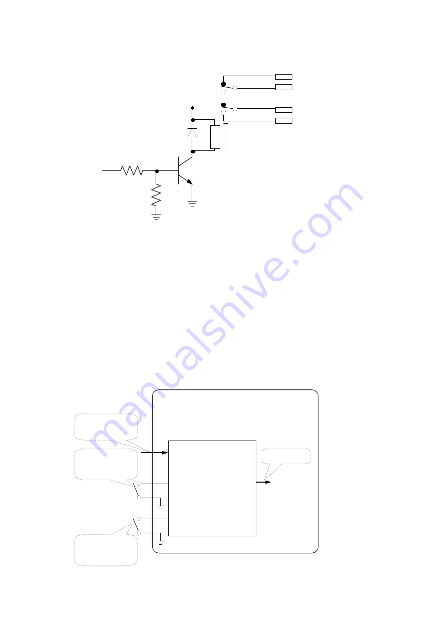
Output Circuit
+12V
100kΩ
10kΩ
O1
B Contact
O1
A Contact
from internal
logic
(9)
(34)
(17)
(42)
same as O2 - O8
Emergency Stop Input Contacts
These contacts are for setting the drive output to zero compulsorily at emergency without using the
software. 25 pin and 50 pin of Remote Control Contact I/O connecter pins are used as Emergency Stop
Input Contacts.
The function of the drive output stop is realized by using the mute function of D/A converter and
reduce the drive output with taking the time of 1024 sampling interval.
Canceling and switching the polarity of Emergency Stop Function are done by DIP switch.
Emergency Stop
Contact
Canceling SW
(Cancelled at close)
Emergency Stop
Signal
I/O Module fundation plate
Emergency Stop
Input Contact
(25/50 pin)
Emergency Stop
Contact
Switching Polarity SW
( + at close)
Содержание K2-CE
Страница 1: ...Vibration Control System K2 CE K2Sprint CE Common Part TYPE II Instruction Manual IMV CORPORATION...
Страница 4: ......
Страница 34: ...2 6 Step 2 The initial screen of installation appears Press the button of Next...
Страница 38: ...2 10 Step 2 The initial screen of installation appears Press the button of Next...
Страница 44: ...2 16 Step 8 The screen of finishing the device driver installation appears Press the button of Finish...
Страница 49: ...2 21 Step 2 The initial screen of installation appears Press the button of Next...
Страница 55: ...2 27 Step 3 The screen displaying the message of Uninstall or change a program appears...
Страница 56: ...2 28 2 Windows 10 Procedures Step 1 Right click the Start Menu And select Control Panel on the displayed menu...
Страница 58: ...2 30 Step 3 The screen displaying the message of Uninstall or change a program appears...
Страница 81: ......
Страница 82: ......
Страница 92: ...4 3 4 2 2 Exit from Application 1 K2 Launcher Press the button Close on the screen...
Страница 107: ...4 18 Step 3 A graph of the page displayed currently appears in the display...
Страница 110: ...4 21 Step 3 Additional graph appears on the currently displayed page...
Страница 115: ...4 26 Step 2 Change values of the graph range for horizontal axis displayed and press the OK button...
Страница 121: ...4 32 Step3 Press the Mark button to mark the cursor data displayed in the list...
Страница 141: ...4 52 Step 2 Press Yes when a dialog of message for assuring appears...
Страница 148: ...4 59 Step 3 Press the Define button of Contact I O information Step 4 Operate the setting of Contact I O and press OK...
Страница 149: ...4 60 Step 5 Press the OK button...
Страница 170: ...4 81 Step 9 Press OK after completing of the necessary settings...
Страница 172: ...4 83 Report of testing result generated by Report Generator...
Страница 184: ...5 6 5 4 1 Initial setting factory setting Factory setting is as shown below To restore it click Initialization...
Страница 189: ...6 5 6 2 2 Display of Standard Graph Procedure Step 1 Press the Open button Step 2 Select the graph data file...
Страница 196: ...6 12 Step 3 Select desired data file Some files can be selected at a time...
Страница 198: ...6 14 Step 5 Graph window is added and the selected graph appears Change of displayed graph Press the graph change button...
Страница 201: ...6 17 Step 3 Select desired data file Some files can be selected at a time...
Страница 212: ...7 6 7 2 2 Standards Mode Procedures Step 1 Press the button of Standards...
Страница 217: ...7 11 7 2 3 Test files mode Procedures Step 1 Press the button of Test files...
Страница 257: ...Waterfall graph depth fixing 4 19 Waterfall graph scroll display 4 19 4 22 4 27 Web Monitor 4 66...


