Chapter 7 Usage of Various Functions
7-
b)
PID8AT instruction parameter setting and explanation.
(a)
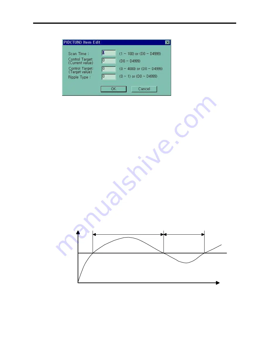
Scan time
S_TIME is the period of reading data (sampling), and 10 times scaled up for more precious operation. Generally,
it should be synchronized with external trigger input to perform proper PID operation.
The range of sampling time is 0.1 ~ 10 seconds, and actual input range is 0 ~ 100.
(b)
Control target(SV)
SV (setting value : the designated value) and PV (process value : present value) of MK80S PID operation have
the range 0 ~ 4000. The range is set with the consideration of the resolution of A/D and D/A module of MK80S
series (12 bits) and offset value. When setting the SV or PV, please be careful convert the analog value of
control object (temperature, velocity, etc.) to digital value that are the output of A/D convert module. For example,
assume that PID control is used for temperature control with Pt100 (operation range : 0
°
C ~ 250
°
C), and the
goal value is 100
°
C. The equivalent digital output of A/D module (voltage output range : 1 ~ 5V) is 1600 if the
A/D module outputs 0 (1V) with 0
°
C, and 4000(5V) with 250
°
C. Therefore, the input of SV should be 1600, not
2.
(c) Ripple type
The K7 perform auto-tuning operation based on the frequency response method. PID parameters are
obtained by On/Off operation during 1 cycle of PV variation. The RIPPLE parameter shows at which cycle the
CPU module will perform auto-tuning operation. If 0 is selected, the CPU will get PID parameters during the first
cycle of PV variation. If 1 is selected, the second cycle will be used. (refer Fig. 3-1 for detailed information) Other
choice of RIPPLE parameter is not allowed. In general case, select 1 for proper auto-tuning operation. The On/Off
operation will be occur at the 80% of PV value.
Fig.3-1 The ripple parameter
80% of PV
Perform A/T operation at the 1
st
cycle
Perform A/T operation at the 2
nd
cycle
Содержание K7 Series
Страница 1: ...User s Manual Programmable Logic Controller IMO K7 IMO Precision Controls...
Страница 21: ...Chapter 4 Names of Parts 4 4 1 2 30 points base unit 4 1 3 40 points base unit 4 1 4 60 points base unit...
Страница 57: ...Chapter 6 Input and Output Modules 6 3 40 point base unit 4 60 point base unit DC24V DC24V DC24V DC24V...
Страница 166: ...Chapter8 Communication Function 8 43 Set parameters like the following table and click OK button Program...
Страница 189: ...Chapter 8 Communication Function 8 66 You can see the framelist which is designated Click OK button...
Страница 234: ......


