9
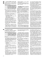
Technische Daten
DMX-Ausgang: . . . . . . . . . XLR, 3- und 5-polig
Pin 1 = Masse
Pin 2 = DMX-Signal -
Pin 3 = DMX-
Pin 4 und 5 = frei
Audio-Eingang: . . . . . . . . . 0,1 – 2 V/22 k
Ω
, stereo,
6,3-mm-Klinke
Musiksteuerung: . . . . . . . . über internes Mikrofon
oder Buchse AUDIO IN
zuweisbare DMX-Adressen: 001 – 144
Steuerkanäle: . . . . . . . . . . . 96
speicherbare Szenen: . . . . 240 (je 12 in 20 Spei-
cherbanken)
speicherbare Sequenzen: . 60 mit max.
120 Schritten
Überblendzeit: . . . . . . . . . . 0 – 25,4 s oder manu-
elle Überblendung mit
Crossfader
Display: . . . . . . . . . . . . . . . LCD, alphanumerisch,
beleuchtet,
2 Zeilen à 16 Zeichen
Stromversorgung: . . . . . . . 230 V~/50 Hz/10 VA
Einsatztemperatur: . . . . . . . 0 – 40 °C
Abmessungen: . . . . . . . . . . 482 x 178 x 85 mm,
4 HE (Höheneinheiten)
Gewicht: . . . . . . . . . . . . . . . 3 kg
Änderungen vorbehalten.
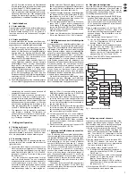
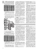
Übersicht der Konfigurationsmöglichkeiten
Erläuterungen zur Abb. 7 auf Seite 19.
Die 96 Steuerkanäle sind in 8 Gruppen unterteilt.
Die Gruppen können einzeln oder auch zu meh-
reren angewählt werden. Dadurch lassen sich
mehrere Geräte zeitweilig gemeinsam steuern.
Die Optionen Masterabhängigkeit (M), Über-
blendbarkeit mit Zwischenwerten (C), Blackout
(B) und Full On/Flash (F) sind für jeden Steuer-
kanal einzeln deaktivierbar (N), wenn die Funk-
tion nicht sinnvoll ist. Voreingestellt ist, dass die
Option aktiviert ist (Y).
Der Steuerhebel MOTION CONTROL lässt sich
für die Kanäle 1/2 und/oder 7/8 einschalten. Je
nach aktivierter Steuerkanalgruppe werden darü-
ber auch die Kanäle 13/14 bzw. 19/20, 25/26
bzw. 31/32 usw. gesteuert.
Ein Vertauschen von Steuerkanälen erspart das
Umstecken von Anschlüssen an schwer zugäng-
lichen Stellen.
Fehlerhafte oder in einer Szene störende Be-
leuchtungskörper können aus der Steuerung her-
ausgenommen werden, indem die DMX-Adresse
dem Steuerkanal 0 zugeordnet wird. Es wird
dann permanent der Wert Null ausgegeben oder
der Wert 255 bei Invertierung (invers = Y).
Mehrere DMX-Adressen können demselben
Steuerkanal zugeordnet und deren Ausgabewerte
dabei individuell invertiert werden. Dadurch lassen
sich z. B. Scanner synchron steuern, bei Invertie-
rung eines Ausgangs auch spiegelsymmetrisch.
Die Funktionen verschiedener DMX-Geräte las-
sen sich zur besseren Übersicht in eine einheit-
liche Reihenfolge ordnen.
Obwohl nur 96 Steuerkanäle zur Verfügung ste-
hen können 144 DMX-Adressen angesprochen
werden, wenn diese abwechselnd oder mehrere
parallel den Steuerkanälen zugeordnet werden.
8
7
6
5
4
3
2
1
9
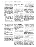
Specifications
DMX output: . . . . . . . . . . . . XLR,3-pole and 5-pole
pin 1 = ground
pin 2 = DMX signal -
pin 3 = DMX
pins 4 and 5: not
connected
Audio input: . . . . . . . . . . . . 0.1 – 2 V/22 k
Ω
,
stereo, 6.3 mm jack
Music control: . . . . . . . . . . . via internal microphone
or jack AUDIO IN
DMX addresses to
be assigned: . . . . . . . . . . . 001 – 144
Control channels: . . . . . . . . 96
Scenes to be memorized: . 240 (12 each in
20 memory banks)
Sequences to
be memorized: . . . . . . . . . . 60 with max.
120 steps
Crossfading time: . . . . . . . . 0 – 25.4 s or manual
crossfading
with crossfader
Display: . . . . . . . . . . . . . . . LCD, alphanumeric,
illuminated,
2 lines of 16 charac-
ters each
Power supply: . . . . . . . . . . 230 V~/50 Hz/10 VA
Ambient temperature: . . . . 0 – 40 °C
Dimensions: . . . . . . . . . . . . 482 x 178 x 85 mm,
4 rack spaces
Weight: . . . . . . . . . . . . . . . . 3 kg
Subject to change.
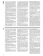
Overview of the Configuration Possibilities
Explanations to fig. 7 on page 19.
The 96 control channels are subdivided into
8 groups. Individual groups or several groups can
be selected. Thus, it is possible to control several
units in common for a time.
The options master depend (M), capability of
crossfading with interim values (C ), blackout (B),
and Full On/Flash (F) can individually be deac-
tivated for each control channel (N) if the function
is not useful. Activation of the option is preset (Y).
The control lever MOTION CONTROL can be
switched on for the channels 1/2 and/or 7/8.
Depending on the activated control channel
group also the channels 13/14 or 19/20, 25/26
or 31/32 etc. are controlled via this lever.
By exchanging control channels, it is not neces-
sary to rearrange connections at places of diffi-
cult access.
Illumination elements which are defective or may
interfere in a scene can be taken out of the con-
trol by assigning the DMX address to the control
channel 0. Then the value 0 is permanently sent
to the output or the value 255 in case of inversion
(inverse = Y).
Several DMX addresses can be assigned to the
same control channel and their output values can
be inverted individually. Thus, e.g. scanners can
be controlled synchronously, in case one output
is inverted, even in a mirror symmetry.
The functions of different DMX units can be
arranged in uniform order for a better overview.
Although only 96 control channels are available,
144 DMX addresses may be approached if they
are assigned to the control channels alternately
or several addresses in parallel
8
7
6
5
4
3
2
1
18
GB
D
A
CH
Diese Bedienungsanleitung ist urheberrechtlich für MONACOR
®
INTERNATIONAL GmbH & Co. KG
geschützt. Eine Reproduktion für eigene kommerzielle Zwecke – auch auszugsweise – ist untersagt.
All rights reserved by MONACOR
®
INTERNATIONAL GmbH & Co. KG. No part of this instruction manual
may be reproduced in any form or by any means for any commercial use.

