12. Register Descriptions
327
PowerSpan II User Manual
80A1010_MA001_09
Integrated Device Technology
www.idt.com
12.5.45
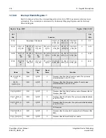
Interrupt Status Register 0
This register is one of two interrupt status registers. ISR0 is used primarily for normal operating status.
When set, each bit of this register indicates the corresponding interrupt source is active.
Register Name: ISR0
Register Offset: 0x410
PCI
Bits
Function
PB
Bits
31-24
ISR1_AC
TV
0
I2O_HOS
T
I2O_IOP
DMA3
DMA2
DMA1
DMA0
0-7
23-16
P2_HW
P1_HW
INT5_
HW
INT4_
HW
INT3_
HW
INT2_
HW
INT1_
HW
INT0_
HW
8-15
15-08
DB7
DB6
DB5
DB4
DB3
DB2
DB1
DB0
16-23
07-00
MBOX7
MBOX6
MBOX5
MBOX4
MBOX3
MBOX2
MBOX1
MBOX0
24-31
Name
Type
Reset
By
Reset
State
Function
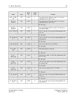
ISR1_ACTV
R
G_RST
0
Indicates an interrupt status bit is set in ISR1 register.
This bit is a logical OR of all the status bits in the ISR1
register. When any status bit in ISR1 is set, ISR1_ACTV is
set. When all bits of the ISR1 register are cleared,
ISR1_ACTV is cleared. This bit is useful in determining
whether or not to read the ISR1 register to determine the
source of the interrupt.
I2O_HOST
R
G_RST
0
Interrupt asserted to the I2O Host to indicate that the
Outbound Post List FIFO contains MFAs of messages for the
Host to process.
This bit is an alias for the I2O Outbound Post List Status
Register located at offset 0x030 of the I2O Target Image.
I2O_IOP
R/Write 1 to
Clear
G_RST
0
Interrupt to embedded PowerPC to indicate that the Inbound
Post List FIFO contains MFAs of messages for the embedded
PowerPC to process.
DMAx
R/Write 1 to
Clear
G_RST
0
Set when DMAx generates an interrupt. See DMAx_GCSR
register for details.
P1_HW
R/Write 1 to
Clear
G_RST
0
PCI-1 hardware interrupt. Set when a level interrupt is
detected on the PCI-1 INTA# pin.
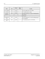
P2_HW
R/Write 1 to
Clear
G_RST
0
PCI-2 hardware interrupt. Set when a level interrupt is
detected on the PCI-2 INTA# pin.
Single PCI PowerSpan II: Reserved
Содержание PowerSpan II
Страница 8: ...Contents 8 PowerSpan II User Manual 80A1010_MA001_09 Integrated Device Technology www idt com ...
Страница 14: ...List of Tables 14 PowerSpan II User Manual 80A1010_MA001_09 Integrated Device Technology www idt com ...
Страница 18: ...About this Document 18 PowerSpan II User Manual 80A1010_MA001_09 Integrated Device Technology www idt com ...
Страница 82: ...2 PCI Interface 82 PowerSpan II User Manual 80A1010_MA001_09 Integrated Device Technology www idt com ...
Страница 112: ...3 Processor Bus Interface 112 PowerSpan II User Manual 80A1010_MA001_09 Integrated Device Technology www idt com ...
Страница 156: ...7 Interrupt Handling 156 PowerSpan II User Manual 80A1010_MA001_09 Integrated Device Technology www idt com ...
Страница 380: ...12 Register Descriptions 380 PowerSpan II User Manual 80A1010_MA001_09 Integrated Device Technology www idt com ...
Страница 394: ...14 Package Information 394 PowerSpan II User Manual 80A1010_MA001_09 Integrated Device Technology www idt com ...
Страница 414: ...15 AC Timing 414 PowerSpan II User Manual 80A1010_MA001_09 Integrated Device Technology www idt com ...
Страница 416: ...16 Ordering Information 416 PowerSpan II User Manual 80A1010_MA001_09 Integrated Device Technology www idt com ...
Страница 420: ...A Hardware Implementation 420 PowerSpan II User Manual 80A1010_MA001_09 Integrated Device Technology www idt com ...
Страница 428: ...B Typical Applications 428 PowerSpan II User Manual 80A1010_MA001_09 Integrated Device Technology www idt com ...
Страница 432: ...Glossary 432 PowerSpan II User Manual 80A1010_MA001_09 Integrated Device Technology www idt com ...


