P
P
a
a
g
g
e
e
3
3
5
5
4.3
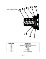
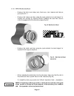
Product Seal Fitting and Removal.
4.3.1 General Procedures for Installing Seals.
-
Mechanical seals are precision-engineered assemblies incorporating finely
lapped seal faces and seats. They must, therefore, be handled with care
and will not give optimum performance unless installed carefully and
according to instructions.
-
Where mechanical seals are to be reused ensure that seal component is
kept in their appropriate sets.
Do not mix old and new seal faces on the
same seal.
-
Remove any sharp corners and burrs that may damage any elastomers
such as O-rings or lip seals.
-
Ensure that all seal component fitting bores and housings are thoroughly
cleaned before installation.
-
The seal faces and seats must be handled with care and cleaned
thoroughly before installation.
-
Ensure that seal faces are undamaged, and the O-rings are not cut,
swollen, or cracked.
-
Lip-seals and O-rings within the seal assemblies should be lightly
lubricated with an elastomer compatible, food-grade lubricant. Ensure
there is not an excessive amount of lubricant especially around the seal
face area. Lubrication points are available options, for more information
contact Wright Flow Technologies Limited or your Wright Flow
Technologies Limited distributor.
-
When fitting PTFE encapsulated O-rings, it is important to immerse them
in hot water for several minutes to soften them.
-
Ensure seal seats are mounted squarely.
-
Ensure when installing seals with brittle faces such as silicon carbide that
extra care is taken.
-
Do not use any excessive force to install a mechanical seal. If it is difficult
to position and assemble the seal, then something is wrong.
-
If you drop or damage a seal, do not install it before an inspection has
been carried out.
-
Do not run any seal options dry.
W
W
A
A
R
R
N
N
I
I
N
N
G
G
Содержание Wright Flow Technologies RTP Series
Страница 1: ...P Pa ag ge e 0 0 INSTALLATION OPERATION AND MAINTENANCE MANUAL FOR THE RANGE OF PUMPS...
Страница 47: ...P Pa ag ge e 4 46 6 5 0 Specifications 5 1 Clearance Chart B A C Radial D C Radial...
Страница 51: ...P Pa ag ge e 5 50 0 B B 100 mm or 4 PORT 80 mm or 3 PORT 5 5 RTP30 Foundation Dimensions Stub Shaft Drive...
Страница 54: ...P Pa ag ge e 5 53 3 5 6 Typical Basic Pump Build RTP20 Shown...
Страница 56: ...P Pa ag ge e 5 55 5 5 8 RTPTM Service History Pump Serial No Date Comments...


