P
P
a
a
g
g
e
e
1
1
3
3
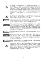
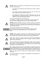
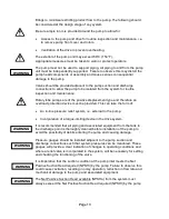
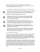
fittings to minimise restricting product flow to the pump. The following should
be considered at the design stage of any system
Be sure ample room is provided around the pump to allow for:
Access to the pump and drive for routine inspection and maintenance, i.e.
to remove pump front cover and rotors.
Ventilation of the drive to prevent overheating.
The exterior of the pump unit may exceed 68
C (154
F),
Appropriate measures must be taken to warn or protect operators.
The pump must not be used to support piping. All piping to and from the pump
unit must be independently supported. Failure to observe this may distort the
pump head components or assembly and cause serious consequential
damage to the pump.
Valves should be provided adjacent to the pump suction and discharge
connections to allow the pump to be isolated from the system for routine
inspection and maintenance.
Rotary lobe pumps are of the positive displacement type and therefore an
overload protection device must be provided. This can take the form of:
An in-line pressure relief system, i.e. external to the pump.
Incorporation of a torque-limiting device in the drive system.
It is recommended that all piping and associated equipment from the tank to
the discharge point is thoroughly cleaned before installation of the pump to
avoid the possibility of debris entering the pump and causing damage.
Pressure gauges should be installed adjacent to the pump suction and
discharge connections such that system pressures can be monitored. These
gauges will provide a clear indication of changes in operating conditions and
where a relief valve is incorporated in the system, will be necessary for setting
and checking the functioning of the valve.
It is imperative that the suction condition at the pump inlet meets the Net
Positive Suction Head required (NPSHr) by the pump. Failure to observe this
could cause cavitation, resulting in noisy operation, reduction in flow rate and
mechanical damage to the pump and associated equipment.
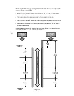
The Net Positive Suction Head available (NPSHa) from the system must
always exceed the Net Positive Suction Head required (NPSHr) by the pump
W
W
A
A
R
R
N
N
I
I
N
N
G
G
W
W
A
A
R
R
N
N
I
I
N
N
G
G
W
W
A
A
R
R
N
N
I
I
N
N
G
G
W
W
A
A
R
R
N
N
I
I
N
N
G
G
W
W
A
A
R
R
N
N
I
I
N
N
G
G
Содержание Wright Flow Technologies RTP Series
Страница 1: ...P Pa ag ge e 0 0 INSTALLATION OPERATION AND MAINTENANCE MANUAL FOR THE RANGE OF PUMPS...
Страница 47: ...P Pa ag ge e 4 46 6 5 0 Specifications 5 1 Clearance Chart B A C Radial D C Radial...
Страница 51: ...P Pa ag ge e 5 50 0 B B 100 mm or 4 PORT 80 mm or 3 PORT 5 5 RTP30 Foundation Dimensions Stub Shaft Drive...
Страница 54: ...P Pa ag ge e 5 53 3 5 6 Typical Basic Pump Build RTP20 Shown...
Страница 56: ...P Pa ag ge e 5 55 5 5 8 RTPTM Service History Pump Serial No Date Comments...


