P
P
a
a
g
g
e
e
2
2
1
1
* N/A = Option not available.
Note: For all other dimensions see section 5.5.
3.8
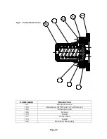
Integral Pressure Relief Valve.
Integral pressure relief valves are normally used to protect the pump from the
effects of increases in system pressure caused, for example, by a restricted or
closed discharge line. In response to a pressure increase, the valve opens and
internally circulates the pumped media within the pump chamber.
When the valve opens, because the volume of fluid circulating is relatively
small, the temperature of the fluid in the pump chamber may rise if the pump
continues to operate for an extended period. In severe cases, this may result
in temperatures in excess of the pumps operating limits or vaporisation of the
fluid. For these reasons when the valve has activated the cause of the system
pressure increase should be eliminated as continuous operation of the pump
with the valve open is not recommended and may cause severe damage to
the pump.
If the pump on which the valve is installed is to be installed in either a
pressurised system or one incorporating a vessel under vacuum, the
application of the valve should be referred to Wright Flow Technologies
Limited or their authorised distributor. In addition to where the pump is
mounted onto a mobile unit with drive, it is recommended that an integral
pressure relief valve is installed.
Note: Care should be taken not to exceed either the pumps maximum
pressure rating or the system design pressure.
The spring housing component including spring, stem and valve; are
manufactured as complete units and available in 7, 10 and 12 bar options.
This must be specified at the time of order. If further adjustment is required to
the assemblies consult Wright Flow Technologies Limited or your local Wright
Flow Technologies Limited distributor.
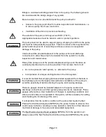
W
W
A
A
R
R
N
N
I
I
N
N
G
G
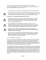
W
W
A
A
R
R
N
N
I
I
N
N
G
G
Содержание Wright Flow Technologies RTP Series
Страница 1: ...P Pa ag ge e 0 0 INSTALLATION OPERATION AND MAINTENANCE MANUAL FOR THE RANGE OF PUMPS...
Страница 47: ...P Pa ag ge e 4 46 6 5 0 Specifications 5 1 Clearance Chart B A C Radial D C Radial...
Страница 51: ...P Pa ag ge e 5 50 0 B B 100 mm or 4 PORT 80 mm or 3 PORT 5 5 RTP30 Foundation Dimensions Stub Shaft Drive...
Страница 54: ...P Pa ag ge e 5 53 3 5 6 Typical Basic Pump Build RTP20 Shown...
Страница 56: ...P Pa ag ge e 5 55 5 5 8 RTPTM Service History Pump Serial No Date Comments...

