


Removing the Emulex 10GbE Custom Adapter for IBM System x
or the Emulex 10GbE Integrated Virtual Fabric Adapter II for IBM
System x
To remove the Emulex 10GbE Custom Adapter for IBM System x or the Emulex
10GbE Integrated Virtual Fabric Adapter II for IBM System x, complete the
following steps:
1.
Read the safety information and installation guidelines, see “Safety” on page vii
and “Installation guidelines” on page 261.
2.
Turn off the server (see “Turning off the server” on page 17) and all attached
peripheral devices. Disconnect all power cords; then, disconnect all external
cables as necessary to replace the device.
3.
Remove the top cover (see “Removing the server top cover” on page 264).
4.
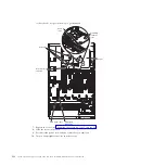
If any adapters are installed in the three-slot PCI riser-card assembly,
disconnect any cables that are connected to the adapters.
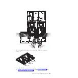
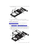
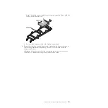
5.
Carefully grasp the riser card and pull it until it disengages from the riser card
connector on the system board.
6.
Pull the Emulex adapter out of the riser card.
7.
If you are instructed to return the adapter, follow all packaging instructions,
and use any packaging materials for shipping that are supplied to you.
Replacing the Emulex 10GbE Custom Adapter for IBM System x
or the Emulex 10GbE Integrated Virtual Fabric Adapter II for IBM
System x
To replace a Emulex 10GbE Custom Adapter for IBM System x or the Emulex
10GbE Integrated Virtual Fabric Adapter II for IBM System x, complete the
following steps:
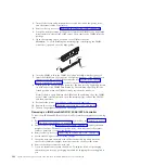
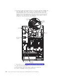
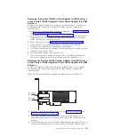
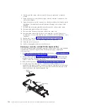
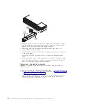
Note:
The following illustration might differ slightly from your hardware.
SFP module
(port 0)
SFP module
(port 1)
1.
Read the safety information that begins on page “Safety” on page vii and
“Installation guidelines” on page 261.
2.
Touch the static-protective package that contains the new adapter to any
unpainted metal surface on the server. Then, remove the adapter from the
package.
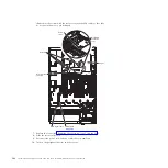
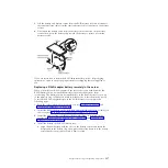
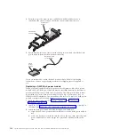
3.
Insert the adapter into the riser-card assembly, aligning the edge connector on
the adapter with the connector on the riser-card assembly. Press the edge of
Chapter 5. Removing and replacing components
313
Содержание System x3690 X5
Страница 1: ...System x3690 X5 Types 7147 7148 7149 and 7192 Problem Determination and Service Guide...
Страница 2: ......
Страница 3: ...System x3690 X5 Types 7147 7148 7149 and 7192 Problem Determination and Service Guide...
Страница 8: ...vi System x3690 X5 Types 7147 7148 7149 and 7192 Problem Determination and Service Guide...
Страница 13: ...Safety statements Safety xi...
Страница 22: ...4 System x3690 X5 Types 7147 7148 7149 and 7192 Problem Determination and Service Guide...
Страница 266: ...248 System x3690 X5 Types 7147 7148 7149 and 7192 Problem Determination and Service Guide...
Страница 278: ...260 System x3690 X5 Types 7147 7148 7149 and 7192 Problem Determination and Service Guide...
Страница 386: ...368 System x3690 X5 Types 7147 7148 7149 and 7192 Problem Determination and Service Guide...
Страница 407: ...1 2 Chapter 5 Removing and replacing components 389...
Страница 444: ...426 System x3690 X5 Types 7147 7148 7149 and 7192 Problem Determination and Service Guide...
Страница 453: ...People s Republic of China Class A electronic emission statement Taiwan Class A compliance statement Notices 435...
Страница 454: ...436 System x3690 X5 Types 7147 7148 7149 and 7192 Problem Determination and Service Guide...
Страница 461: ...weight of memory enclosure 28 Index 443...
Страница 462: ...444 System x3690 X5 Types 7147 7148 7149 and 7192 Problem Determination and Service Guide...
Страница 463: ......
Страница 464: ...Part Number 47C8865 Printed in USA 1P P N 47C8865...