


d. Reinstall the two screws that you removed in
step 4a to secure the fan guard.
7. Touch the static-protective package containing the
new processor daughterboard to any
unpainted metal
surface on the server; then, remove the new
processor daughterboard
.7/
from its static-protective
package.
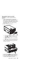
8. Align the processor-daughterboard connector with the
keyed connector on the processor controller board.
Note
For the location of the processor-daughterboard
connectors on the processor controller board, see
“Processor-controller board component locations”
on page 140. For a layout of the processor
daughterboard, see “Processor-daughterboard
component locations” on page 143.
9. Firmly press the processor daughterboard
.7/
down
into the keyed connector on the processor controller
board. Push in the center of the board, until the
processor daughterboard is fully seated.
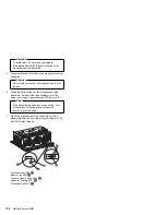
10. Ensure that the two processor cage release latches
are still in the unlocked (pulled out) position.
11. Align the processor cage with its tabs over the
corresponding slots on the processor daughterboard.
Match the labels on the processor cage with the
corresponding labels on the fan guard
.9/
; for
example, A1/A1.
12. Firmly press the processor cage down into the slots in
the processor housing assembly, until the processor
cage is fully seated.
13. Squeeze and firmly push the release latches
.1ð/
back into the locked position; then, release.
Attention
Ensure that the release latches are in the fully
locked position.
14. Install processors
.4/
in the desired connectors, as
described in step 3 on page 151 through step 7 on
page 153; then, return here.
15. Install terminator cards
.3/
in the connectors that do
not contain processors. The arrows on the
terminators must face toward the large connector on
the processor housing assembly and away from the
fan guard.
16. Reinstall the processor-cage cover by reversing step
2 on page 155.
17. Reinstall the processor housing assembly by
performing steps 1 through 7 on page 159.
Replacing the standard processor
daughterboard:
To replace the processor
daughterboard in the standard processor cage:
156
Netfinity Server HMM
Содержание 8500R - Netfinity - 8681
Страница 2: ......
Страница 8: ...vi Netfinity Server HMM...
Страница 25: ...1 LVD low voltage differential Netfinity 8500R Type 8681 17...
Страница 62: ...Caution Use safe practices when lifting 54 Netfinity Server HMM...
Страница 240: ...Processor Housing Assembly A1 A2 A3 A4 B1 B2 B3 B4 B1 B2 B3 B4 A3 A4 A2 A1 1 2 3 4 5 6 7 8 9 232 Netfinity Server HMM...
Страница 242: ...I O Housing Assembly 1 2 3 4 5 6 7 234 Netfinity Server HMM...
Страница 261: ...Related service information 253...
Страница 262: ...254 Netfinity Server HMM...
Страница 263: ...Related service information 255...
Страница 264: ...256 Netfinity Server HMM...
Страница 265: ...Related service information 257...
Страница 278: ...270 Netfinity Server HMM...
Страница 279: ...Related service information 271...
Страница 280: ...272 Netfinity Server HMM...
Страница 290: ...IBM Part Number 37L5123 Printed in U S A S37L 5123...