background image


Hot-swap power supply
installation/removal

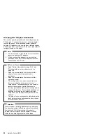
  Danger 

Overloading an electrical circuit breaker is potentially a
fire hazard and a shock hazard under certain
conditions. To avoid these hazards, adhere to the
instructions in the following statements.

1. If you are connecting to a 100–127 V AC power

source, connect each power cord to a separate
branch circuit.

2. If you are connecting to a 200–240 V AC power

source and the branch circuit breaker rating is:

a. 13 amps or less, connect each power cord

to a separate branch circuit.

b. 14 amps to 19 amps, do not connect more

than two power cords to the same branch
circuit.

c. 20 amps or greater, you may connect up to

three power cords to the same branch
circuit.

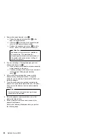
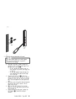
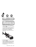
The server comes with three power supplies, three 220 V
AC power cords, and three 110 V AC power cords (U.S.
only). Be sure to select the appropriate power cord
voltage for the server environment. All three power cords
must have the same voltage.

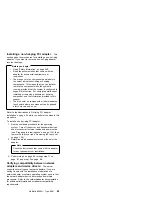
If you connect the three:

Ÿ

220 V AC power cords to the power supplies, the
three power supplies support redundancy and
hot-swap capability.

Ÿ

110 V AC power cords to the power supplies, the
three power supplies do not support redundancy if the
system configuration exceeds any of these conditions:

More than six processors

More than 24 memory DIMMs

More than eight PCI adapters

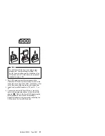
For servers with redundant power, the loss of a single
power supply will not affect the server operation. Replace
a power supply that has failed as soon as convenient to
help maintain the redundant power and cooling capability.
When the AC power LED is on, the DC power LED is on,
and the System Power light on the operator panel is on,
the power supply has failed. See “Hot-swap Power
supplies” on page 80 for the location of the DC power
LEDs. See “Power supply LED errors” on page 173 for
more information on the DC power LEDs.


92

Netfinity Server HMM 


Содержание 8500R - Netfinity - 8681

Страница 1: ...S37L 5123 00 IBM Netfinity Servers IBM Netfinity 8500R Type 8681 Models 4RY 4RG 5RY 5RG 6RY 6RG Hardware Maintenance Manual September 1999 We Want Your Comments Please see page 277...

Страница 2: ......

Страница 3: ...S37L 5123 00 IBM Netfinity Servers IBM Netfinity 8500R Type 8681 Models 4RY 4RG 5RY 5RG 6RY 6RG Hardware Maintenance Manual September 1999 We Want Your Comments Please see page 277 IBM...

Страница 4: ...rmation herein these changes will be incorporated in new editions of the publication IBM may make improvements and or changes in the product s and or the program s described in this publication at any...

Страница 5: ...familiar with IBM PC Server products Important safety information Be sure to read all caution and danger statements in this book before performing any of the instructions Leia todas as instru es de c...

Страница 6: ...a cabo cualquier operaci n Online support Use the World Wide Web WWW to download Diagnostic BIOS Flash and Device Driver files File download address is http www ibm com pc files html IBM online addres...

Страница 7: ...15 Configuring the server 18 Specifications 40 Locations 42 Symptom to FRU index 166 Undetermined problems 211 Parts listing Netfinity 8500R Type 8681 229 Related service information 239 Safety inform...

Страница 8: ...vi Netfinity Server HMM...

Страница 9: ...ion overview 19 The Configuration Setup Utility program 20 Using the Configuration Setup Utility main menu 21 System summary 23 System information 23 Product data 23 System card data 23 Devices and I...

Страница 10: ...rdware 52 Lifting the server 53 CD ROM drive removal 55 Completing the installation 56 Installing the top cover 56 Installing the front bezel 58 Reconfiguring the server and updating server records 59...

Страница 11: ...ut connectors and expansion slots 122 Jumper settings 125 Two pin jumper blocks 125 Three Pin jumper blocks 126 LED card removal 129 Memory board component locations 130 Midplane removal 132 Power con...

Страница 12: ...ors 173 AC LED on DC LED off 174 Power control card LED 176 Server component fault indicators 182 Diagnostic error codes 183 Other error symptoms 190 POST error codes 194 DASD LEDs for hardfiles runni...

Страница 13: ...y clear any messages from the front panel display using the scroll and enter buttons on the right side of the front panel after you have replaced any FRU s This can be done with the system in the Stan...

Страница 14: ...t fault indicators on page 182 10 If you have a flashing attention light and error messages posted in the front panel see System management codes on page 222 11 If you have run diagnostics which gener...

Страница 15: ...e System management codes on page 222 Attempt to boot to the Configuration Setup utility and check the system error log If an error was recorded by the system see Symptom to FRU index on page 166 If t...

Страница 16: ...confirm that the hardware is working properly Note When you run the diagnostic programs a single problem might cause several error messages When this occurs work to correct the cause of the first err...

Страница 17: ...generates beep codes to indicate successful completion or the detection of a problem One beep indicates the successful completion of POST No beep indicates that a unrecoverable error occurred during P...

Страница 18: ...on on how to view the POST error log System error log The system error log contains all error and warning messages issued during POST all system status messages from the Advanced System Management PCI...

Страница 19: ...System Management PCI Adapter in conjunction with the Advanced System Management service capabilities of Netfinity Manager a terminal program or a Web browser Refer to the Advanced System Management I...

Страница 20: ...your IBM reseller or IBM marketing representative 5 You might need a scratch diskette to obtain accurate test results when testing the diskette drive 6 The keyboard and mouse pointing device tests ass...

Страница 21: ...the tests have completed you can view the Test Log by selecting Utility from the top of the screen Also you can view server configuration information such as system configuration memory contents inte...

Страница 22: ...th step 1 in this procedure If you have not run the diagnostic programs follow the instructions in Starting the diagnostic programs on page 12 then return here To view the Test Log 1 Select Utility fr...

Страница 23: ...0 registered synchronous dynamic random access memory SDRAM with ECC Support for 128 MB 256 MB and 512 MB DIMMs Support for a second memory board optional Diskette drive Supports one diskette drive St...

Страница 24: ...er supplies standard Redundant power available Hot swap capable Auto sensing function Built in overload and surge protection Automatic restart after a loss of power Predictive Failure Analysis PFA ale...

Страница 25: ...1 LVD low voltage differential Netfinity 8500R Type 8681 17...

Страница 26: ...you can set the system date and time define input and output device parameters and define system security Note The illustrations in this chapter might differ slightly from your hardware This section...

Страница 27: ...tion Note The screen might look slightly different depending on the BIOS version that comes with the server and the hardware configuration IBM Netfinity BIOS Copyright IBM Corporation 1999 Press F1 fo...

Страница 28: ...tions are typically but not always required to configure the server 1 Run the Configuration Setup Utility program and record the current configuration settings 2 Set jumpers or switches on server comp...

Страница 29: ...logo screen If the server is turned on already shut down the operating system and restart the server 3 After you start the server several prompts appear on the IBM logo screen When the prompt Press F...

Страница 30: ...ess Esc to return to the Configuration Setup Utility main menu 4 After making changes you can select Save Settings to save the selected changes Restore Settings to delete the changes and restore the p...

Страница 31: ...ity 8500R server components Devices and I O ports Software recognizes ports through their port assignments Each port must have a unique port assignment The Configuration Setup Utility program normally...

Страница 32: ...h Day Year Select Date and Time then use the Left Arrow or Right Arrow key to advance through each data field Type the new information the system saves the information as you type it The Date and Time...

Страница 33: ...een set you must enter the administrator password when you run the flash update program You must enter this password to enable system security feature Intrusion detection tower configuration only will...

Страница 34: ...to the Enter Power on Password Again data field and type the password again Note A message appears if the two passwords do not match If this happens press Esc to cancel the request and return to the S...

Страница 35: ...ny combination of up to seven alphanumeric characters A Z a z and 0 9 Keep a record of your password in a secure place 3 Move the cursor to the Enter Administrator Password Again data field and type t...

Страница 36: ...e the device from which the operating system loads For example you can define a startup sequence that checks for a startable diskette in the diskette drive then checks the hard disk drive in bay 1 and...

Страница 37: ...led Enabling the processor serial number access feature changes the server configuration Therefore after you enable this feature save the new configuration information in the Configuration Setup Utili...

Страница 38: ...licts on page 34 Use the Up Arrow or Down Arrow key to highlight the assignment that you want to change and press Enter Use the Left Arrow or Right Arrow key to select from the list of available choic...

Страница 39: ...roblem is corrected You can diagnose to just one DIMM To manually enable a DIMM slot 1 Select Memory Settings from the Advanced Setup menu 2 Use the Up Arrow or Down Arrow key to highlight the DIMM sl...

Страница 40: ...rning messages that the system has generated You can use the Up Arrow or Down Arrow keys to move between pages in the system error log Save settings After you make configuration changes review them to...

Страница 41: ...drive If the diskette drive contains a diskette remove it 2 Turn on the server and watch for the IBM logo screen If the server is turned on already shut down the operating system and restart the serv...

Страница 42: ...y to write to the same address space A device resource is changed for example changing jumper settings A device function is changed for example assigning COM1 to two serial ports A software program is...

Страница 43: ...rdware options might conflict with addresses defined for use through application programs or the expanded memory specification EMS EMS is used only with DOS If a conflict exists one or more of the fol...

Страница 44: ...Use the Up Arrow or Down Arrow key to move the highlight bar to the various menu choices Press Esc to return to the previous menu Also you can press the F5 key to switch between color and monochrome m...

Страница 45: ...s Advanced Configuration Options Select this choice to view or change the settings for advanced configuration options These options include enabling support for large hard disk drives and support for...

Страница 46: ...the SCSISelect Utility program to perform a low level format on a hard disk drive The amount of processing time that the low level format program requires will vary according to the hard disk drive ca...

Страница 47: ...k drive 2 Select Format Disk then follow the instructions on the screen Note Hard disks normally contain more tracks than their stated capacity to allow for defective tracks A message appears on the s...

Страница 48: ...range Minimum 180 V AC Maximum 265 V AC Input kilovolt amperes KVA approximately Minimum configuration as shipped 0 5 KVA Maximum configuration 2 1 KVA Environment Air temperature System on 10 to 35 C...

Страница 49: ...m configuration 1700 Btu hr Maximum configuration 7000 Btu hr Safety standards UL 1950 Third Edition CSA C22 2 No 950 95 EN 60950 and countries deviations IEC 950 NOM 019 Notes 1 These levels are meas...

Страница 50: ...e 96 Internal drives installation on page 110 I O board component locations on page 116 I O board removal on page 117 I O function card component locations on page 120 Input output connectors and expa...

Страница 51: ...nd restarting the system These slots are called hot pluggable PCI slots They are also referred to as hot plug PCI slots A PCI adapter comes with built in identification and configuration specification...

Страница 52: ...fail LED for PCI slot green blink attention amber defective PCI adapter 13 Hot plug power LED for PCI slot green solid on PCI slot LED descriptions Each PCI slot has two lights associated with it one...

Страница 53: ...ter around the resources already in use by other devices The default setting is generally the most appropriate If you choose to manually assign interrupts be sure that these interrupts do not conflict...

Страница 54: ...dapter for information about required system resources Then make the appropriate jumper or switch settings on the adapter Table 1 PCI adapter information Bus Slots Speed PCI slot keying A 10 12 33 MHz...

Страница 55: ...the connectors for the 10 100 Mbps Ethernet port dual serial port Advanced System Management Interconnect bus Personal Computer Memory Card International Association PCMCIA token ring and the I O fun...

Страница 56: ...onnector J8 2 Dual serial port connector J11 3 Advanced System Management Interconnect RS 485 bus connector J16 4 External power supply connector 12 V DC jack J19 not used 5 PCMIA token ring connector...

Страница 57: ...33 for information on battery disposal To order replacement batteries call 1 800 388 7080 within the United States and 1 800 465 7999 or 1 800 465 6666 within Canada Outside the U S and Canada call yo...

Страница 58: ...ction card connector side up on a flat static protective surface 3 Locate the battery on the I O function card see I O function card component locations on page 120 4 Remove the battery a Use one fing...

Страница 59: ...emoved in step 2d on page 50 by pressing in the fastener on the bracket f Insert the two screws that you removed in step 2c on page 50 g Connect the cables that you disconnected in step 2b on page 50...

Страница 60: ...the installation or removal of these components These components are known as hot swappable components and more commonly referred to as hot swap components Hot plug means that you can install or remo...

Страница 61: ...under Safety information on page 240 and Working inside a server with power on on page 165 These guidelines will help you work safely while working with the server or options Read the information in...

Страница 62: ...Caution Use safe practices when lifting 54 Netfinity Server HMM...

Страница 63: ...134 before removing or installing options To remove the CD ROM drive 1 Remove the front bezel See Removing the front bezel on page 137 for instructions 2 Disconnect all cables 3 Squeeze latches 1 in...

Страница 64: ...operation If the server is on do not leave the top cover off for more than 30 minutes at a time 2 If necessary see Input output connectors and expansion slots on page 122 for connector locations To i...

Страница 65: ...connecting to a 200 240 V AC power source and the branch circuit breaker rating is a 13 amps or less connect each power cord to a separate branch circuit b 14 amps to 19 amps do not connect more than...

Страница 66: ...l 1 Insert the bottom tabs of the bezel in the matching slots in the server chassis 2 Press in the tab on the bezel then pivot the top of the bezel until the latches 1 snap into place This places the...

Страница 67: ...on Processors The Netfinity 8500R server comes with at least one processor installed on the standard processor daughterboard If you have installed one or more additional processors the server can now...

Страница 68: ...e action You can select Keep to retain the message on the front panel and enable the system error light to continue to flash Remind to retain the message on the front panel and enable the system error...

Страница 69: ...ton to eject a diskette from the drive 9 Diskette drive in use light When this light is lit the diskette drive is being accessed 1 Power control button Press this button to manually turn the server on...

Страница 70: ...rating system hangs Note After turning off the server wait at least five seconds before pressing the Power Control button to power on the server again Disconnecting all of the server power cords from...

Страница 71: ...inline memory modules DIMMs The server uses 100 MHz 168 pin PC100 registered synchronous dynamic random access memory SDRAM industry standard DIMMs with error checking and correction ECC You can add...

Страница 72: ...nly occur if two memory boards are installed in the server This process allows the two memory boards to share a common address range with one memory board responding to even numbered cache lines and t...

Страница 73: ...Ms support the registered mode of operation 2 Install DIMMs with a maximum height of 4 32 cm 1 7 inches 3 The server comes with one standard preinstalled memory board A and one or more DIMMs installed...

Страница 74: ...see Removing the front bezel on page 137 and the memory access panel see Removing the memory access panel on page 138 2 If you are not installing an optional memory board continue with step 3 If you...

Страница 75: ...connector side up on a flat static protective surface 4 Touch the static protective package containing the DIMM to any unpainted metal surface on the server Then remove the DIMM from the package Netf...

Страница 76: ...board a Insert the memory board into the guides and gently press the memory board into the connector When you install the memory board in the server be sure that it is correctly seated in the connecto...

Страница 77: ...tions To remove a diskette drive 1 Remove the front bezel See Removing the front bezel on page 137 for instructions 2 Disconnect all cables 3 Squeeze latch 1 on bottom of drive inward to release the d...

Страница 78: ...m length of SCSI cable between the terminated ends of the cable see the following ANSI SCSI Standards X3 131 1986 SCSI X3 131 1994 SCSI 2 X3T10 1071D X3T10 1142D Ultra 2 SCSI X3 302 1998 Ultra 2 SCSI...

Страница 79: ...ocations of the connectors These ports are used to communicate with printers plotters external modems scanners and auxiliary terminals You can also use these ports to transfer data between computers S...

Страница 80: ...er to Input output connectors and expansion slots on page 122 for the location of the connector 13 1 25 14 The following table shows the pin number assignments for the parallel port connector When you...

Страница 81: ...p to 16 000 000 colors 800 600 pels with up to 16 000 000 colors 1024 768 pels with up to 16 000 000 colors 1152 864 pels with up to 16 000 000 colors 1280 1024 pels with up to 64 000 colors 1600 1200...

Страница 82: ...rnal connector for support of external devices Each controller supports up to 15 SCSI devices You can use the 68 pin SCSI connectors for these controllers to expand the capabilities of the server by a...

Страница 83: ...45 DB5 12 DB6 46 DB6 13 DB7 47 DB7 14 DBP 48 DBP 15 Ground 49 Ground 16 Ground 50 Cable Detect 17 Termpwr 51 Termpwr 18 Termpwr 52 Termpwr 19 Ground 53 Reserved 20 Ground 54 Ground 21 ATN 55 ATN 22 G...

Страница 84: ...ed the device must be connected to a hub Table 9 shows the pin number assignments for the USB connectors Advanced System Management PCI Adapter 10 100 Mbps Ethernet port The Advanced System Management...

Страница 85: ...ain a listing of compatible modems and related information by accessing the following address http www ibm com pc us compat on the World Wide Web Advanced System Management Interconnect port The Advan...

Страница 86: ...Table 11 Advanced System Management Interconnect bus connector pin number assignments Pin Signal 1 Term power 2 Input 3 Input 4 Output 5 Output 6 Ground 78 Netfinity Server HMM...

Страница 87: ...occurs Information about the condition displays on the information message panel 3 SCSI hard disk drive in use light This green light is on when there is activity on a hard disk drive Attention If the...

Страница 88: ...the power supplies the server comes with three 220 V AC power cords and three 110 V AC power cords U S only Be sure to select the appropriate power cord voltage for the server environment All three po...

Страница 89: ...g the server in and removing the server from the rack enclosure on page 96 for additional information on installing a server rack 2 Power cords vary by country For complete details about power cords f...

Страница 90: ...cated closest to the power supply connector During normal operation both the AC and DC power lights are on For any other combination of lights see Power supply LED errors on page 173 3 Power supply co...

Страница 91: ...s 1 The illustrations in this section might differ slightly from your hardware 2 You do not need to turn off the power to the server to replace a fan 3 Replace a fan that has failed as soon as conveni...

Страница 92: ...ith the adapter for any special requirements or restrictions Read the documentation that comes with the operating system The orange color on components and labels in the server indicates hot swap or h...

Страница 93: ...age 136 Attention If the server is on do not leave the top cover off for more than 30 minutes at a time 2 Determine which expansion slot you will use for the adapter Note Check the instructions that c...

Страница 94: ...n assembly where indicated by the arrow b Continue pressing on the assembly as described in step 5a and lift the adapter retention cover 4 6 Refer to the documentation that comes with the adapter for...

Страница 95: ...adapter b Press the adapter firmly into the expansion slot c If you are installing a full length adapter close the adapter retention cover 4 d Lower the tab 1 over the adapter Rotate the adapter reten...

Страница 96: ...13 If you have other options to install or remove do so now otherwise continue with Completing the installation on page 56 88 Netfinity Server HMM...

Страница 97: ...CI adapter installation on page 84 while you perform the steps in this procedure To install a non hot plug PCI adapter 1 Run the shutdown procedure for the operating system Turn off the server and per...

Страница 98: ...e cable routing that is necessary when you install the ServeRAID adapter Refer to the following illustration while you perform the steps in this procedure Notes 1 It might be easier for you to route t...

Страница 99: ...d that is closer to the connector on the end of the cable If necessary refer to the illustration at the beginning of this procedure 4 Install the ServeRAID adapter in PCI slot 10 11 or 12 5 Connect th...

Страница 100: ...the appropriate power cord voltage for the server environment All three power cords must have the same voltage If you connect the three 220 V AC power cords to the power supplies the three power suppl...

Страница 101: ...ing the server in and removing the server from the rack enclosure on page 96 for additional information on installing a server rack Refer to the following illustration while performing the steps in th...

Страница 102: ...r right side and remove the strain relief bracket c Press the release latch 1 on the handle 3 on the power supply 2 d Lift and fully extend the handle on the power supply Then slide the power supply o...

Страница 103: ...power supply in the locked position e Reconnect the power cord to the power supply and the electrical outlet if removed f Remove the new strain relief bracket from its package and install it on the p...

Страница 104: ...server To install the Netfinity 8500R in a rack enclosure the enclosure must have a minimum clearance of 203 2 mm 8 in between the rear of the chassis and the surface of the rear door when the door i...

Страница 105: ...ure In this section you will use the following components IBM installation template Four lift handles Two slide rail latch assemblies left and right Two latch brackets used with the slide rail latch a...

Страница 106: ...Mark the location of all the holes on the rear of the server for the slide rail assemblies and the cable management arm attachment bracket Note Some racks come with cage nuts for the mounting rails wh...

Страница 107: ...ail assembly align the holes marked R for right over the cage nuts or clip nuts b If required loosen the nuts 2 on the rear section of the assembly and adjust the slide rail assembly to fit over the f...

Страница 108: ...escribed in steps 3a through 3f h Press the slide rail assemblies toward the mounting rails and tighten all screws 4 Attach the cable management arms upper and lower a Position the cable management ar...

Страница 109: ...er rigid cable management arm to the slide rail assembly using one of the hinge pins 3 e Connect the two rigid cable management arms with the flexible shaft using one of the hinge pins 4 Netfinity 850...

Страница 110: ...re already not installed on the server install the handles now a Press in on the sides of the lift handle near the tabs and insert the handle tabs into the slots on the sides of the server b Move the...

Страница 111: ...he server to allow you to maneuver the slide rail assembly under the right side tabs after you have the slide rail assembly under the left side tabs 4 Next move the server over the right slide rail as...

Страница 112: ...ver using two screws for each assembly 11 Press the safety latches and slide the server about halfway into the rack enclosure 12 Insert and route the cables on the lower cable management arm first the...

Страница 113: ...n the server Attention When power cords are attached to the rack power distribution unit PDU ensure that the cords are not pinched or chafed by any part of the rack enclosure 14 Use the cable retainer...

Страница 114: ...an area where earthquakes occur or if you plan to move the server you must perform the following step b Install a retaining screw 1 through the hole at the bottom of each of the slide rail latch assem...

Страница 115: ...Shut down the server operating system and remove all media diskettes CDs optical discs or tapes from the drives 3 Turn off the server and any attached devices 4 Disconnect all power cords cables from...

Страница 116: ...e location of the safety latches 9 Locate the four server lift handles 2 that come with the server and attach two lift handles to each side of the server Make sure that the handles lock into place a P...

Страница 117: ...nd off the slide rail assemblies Note Refer to IBM Netfinity Rack to Tower Conversion Kit Installation Instructions for additional information on converting a rack model server to the optional tower c...

Страница 118: ...Several types of drives are available such as Diskette Hard disk CD ROM Some drives have a special design called small computer system interface or SCSI This design allows you to attach multiple drive...

Страница 119: ...us light for a drive is lit continuously that individual drive is defective and needs to be replaced When the hard disk status light indicates a defective drive you can replace a hot swap drive withou...

Страница 120: ...me time The integrated SCSI controllers operate independently If you need to set IDs for SCSI devices refer to the instructions that come with those devices The server automatically sets SCSI IDs for...

Страница 121: ...lling or replacing a drive Notes 1 You do not have to turn off the server to install hot swap drives in these bays If these bays are not connected to a ServeRAID adapter shut down and restart the serv...

Страница 122: ...move the drive from the hot swap bay until it has had time to spin down approximately 30 seconds after disconnecting Handle the drive gently Before you begin Read Safety information on page 240 Read t...

Страница 123: ...e server Then remove the drive assembly from the static protective package c If you are installing a slim high drive separate the slim filler bezel from the tray and insert the slim filler bezel into...

Страница 124: ...itch card connector 7 Hot plug 64 bit PCI slots 10 12 bus A 33 MHz 8 Hot plug 64 bit PCI slots 8 9 bus B 66 MHz 9 Hot plug 64 bit PCI slots 6 7 bus C 66 MHz 1 Hot plug 64 bit PCI slots 1 5 bus D 33 MH...

Страница 125: ...e the I O function card 1 and the Advanced System Management PCI Adapter 2 Remove any other adapters in the system Disconnect all cables To remove the I O function card a Disconnect all cables from th...

Страница 126: ...and pull the I O function card out of the server e Place the I O function card connector side up on a flat static protective surface 3 Remove all insulators 3 See Hot plug PCI adapter installation on...

Страница 127: ...VRM latch releases To remove VRMs from their slots 1 Push latches 1 back 2 Lift VRM 2 up out of its slot 3 Reverse the procedure to insert the VRM into the slot Netfinity 8500R Type 8681 119...

Страница 128: ...I Adapter connector 8 Battery 9 Flash page swap jumper J13 1 Power on password override jumper J14 11 Clear CMOS register contents jumper J15 12 Video port connector note 1 13 Parallel port connector...

Страница 129: ...ing the position of this jumper bypasses the power on password check You do not need to move the jumper back to the default position after the password is overridden Changing the position of this jump...

Страница 130: ...Advanced System Management PCI Adapter 1 External connector knockouts for Advanced System Management PCI Adapter token ring option The chassis has an external connector knockout that can be used when...

Страница 131: ...icated to communication with the Advanced System Management PCI Adapter 7 Advanced System Management Interconnect port connector This connector is used to attach other compatible service processors fo...

Страница 132: ...I slots support hot plug PCI adapters 14 Keyboard port connector The keyboard cable connects here 15 Mouse port connector The mouse cable connects here This port sometimes is called an auxiliary devic...

Страница 133: ...change To change a two pin jumper block continue with Two pin jumper blocks To change a three pin jumper block continue with Three Pin jumper blocks on page 126 Two pin jumper blocks Two pin jumper b...

Страница 134: ...I O function card With the three pin jumper blocks each jumper covers two of the three pins on a pin block You can position the jumper to fit over the center pin and either of the other two pins The f...

Страница 135: ...O function card retention bracket 3 on the right side of the card by pulling out the fastener on the bracket e Carefully grasp the I O function card by its top edge and pull the I O function card out...

Страница 136: ...en you install the I O function card in the server be sure that it is completely and correctly seated Incomplete insertion might cause damage to server components e Reinstall the I O function card ret...

Страница 137: ...ator panel assembly 2 to the server chassis 2 Pull the operator panel out of the slot 3 The LED card 4 is located on the back of the operator panel assembly 4 Remove the two screws 3 which hold the LE...

Страница 138: ...boards Note The memory board might look slightly different depending on the hardware that comes with the server 16 1 1 Midplane connector 2 DIMM connectors J1 J16 See DIMM and memory board installati...

Страница 139: ...e same slot on each memory board for example J1 J1 J5 J5 J9 J9 and so on 5 The connector identifiers located on both the standard A and the optional B memory boards are J1 J16 To distinguish the two m...

Страница 140: ...at the top of the midplane tray 2 which hold the midplane to the server chassis 4 Lift the midplane up out of the chassis 5 Remove the eight screws 6 that hold the midplane card 7 to the midplane tray...

Страница 141: ...al on page 132 for instructions and the illustration on removing the midplane 2 Lift up from the orange plastic pull 3 on the bracket 4 This will lift the bracket clear of the power control card 3 Lif...

Страница 142: ...continue with Hot swap power supply installation removal on page 92 Replacing a processor fan continue with Removing the front bezel on page 137 then go to Hot swap fan installation removal on page 83...

Страница 143: ...telecommunications systems networks and modems before you open the device covers unless instructed otherwise in the installation and configuration procedures Connect and disconnect cables as described...

Страница 144: ...ove the server top cover 1 Unless you are installing or removing a hot swap or hot plug component run the shutdown procedure for the operating system turn off the server and all attached devices and d...

Страница 145: ...this procedure Before you begin Read Safety information on page 240 To remove the front bezel 1 Press on the tabs at the top edge of the bezel 1 2 Pivot the top of the bezel slightly away from the ser...

Страница 146: ...is lit 2 Run the shutdown procedure for the operating system Turn off the server and peripheral devices and disconnect all external cables and power cords see Preparing to install options on page 134...

Страница 147: ...a Ensure that the memory access panel is fully seated in the appropriate location b Press in the two plastic fasteners on the memory access panel to secure it into place Netfinity 8500R Type 8681 139...

Страница 148: ...g illustration 1 Midplane connector 2 Processor cage release latches four 3 Processor daughterboard slot B connector secondary slot 4 Cache coherency filter card connectors 5 Processor core frequency...

Страница 149: ...ver has a 550 MHz processor installed and you install three 600 MHz processors set the processor core frequency selection jumper block for the 550 MHz processor MHz denotes internal clock speed of the...

Страница 150: ...and 13 14 are closed Pins 15 16 are open For the core bus fraction 6 0 600 100 MHz pins 9 10 11 12 and 13 14 are open Pins 15 16 are closed For the core bus fraction 6 5 650 100 MHz pins 9 10 and 15...

Страница 151: ...ghterboard is shown in the following illustration The server supports two processor daughterboards 1 4 2 Processor or processor terminator card connectors A1 A4 or B1 B4 3 Processor controller board c...

Страница 152: ...Align the bottom tabs of the fan 2 with the matching slots in the server chassis 6 Pivot the fan in an upward position 7 When you have the fan correctly seated in the fan bay press on the fastener in...

Страница 153: ...tor on the bottom of the fan with the matching connector in the server chassis 6 When you have the fan correctly seated in the fan bay press down on the fastener in the center of the fan to secure the...

Страница 154: ...a list of supported operating systems see http www ibm com pc us compat on the World Wide Web Before you begin Read Safety information on page 240 Thoroughly review the documentation that comes with t...

Страница 155: ...peeds see http www ibm com pc us support on the World Wide Web 4 To maintain signal quality and system reliability either a processor or a processor terminator card must be installed in each processor...

Страница 156: ...the processor slot in the Configuration Setup utility program In this case the system does not automatically access the Configuration Setup utility program to enable the processor slot See Processor s...

Страница 157: ...emove the three processor fans a Pull the fastener 1 in the top center of the fan housing 2 This places the fastener in the unlocked position b Pivot the fan downward and remove it from the server c R...

Страница 158: ...r housing assembly Lift and slide the assembly out of the server until it stops approximately 228 6 mm 9 in Note If the assembly stops before you can slide it out of the server lift it slightly and co...

Страница 159: ...tches 5 Processor terminator card 6 Processor and heat sink 1 Turn the four plastic fasteners 2 on the processor cage cover 1 until they are in the unlocked position one quarter turn You may use a fla...

Страница 160: ...ow fault on the processor housing assembly b Press the indicated button adjacent to the words Press to show fault and note the amber LEDs that indicate the defective processors if any If no amber LEDs...

Страница 161: ...continue with Installing or replacing a processor daughterboard If you are not installing a processor daughterboard continue with the following steps 10 Reinstall the processor cage cover by inserting...

Страница 162: ...processor cage cover 3 Processor terminator card 4 Optional processor 5 Processor cage 6 Processor daughterboard spacers not present if processor daughterboard is present 7 Processor daughterboard 8...

Страница 163: ...ving the processor cage from the processor housing assembly be sure that the processor cage release latches remain in place Store the spacers in a safe place for future use 4 Remove the fan guard 9 a...

Страница 164: ...on 11 Align the processor cage with its tabs over the corresponding slots on the processor daughterboard Match the labels on the processor cage with the corresponding labels on the fan guard 9 for exa...

Страница 165: ...remove the processor Place it on a flat static protective surface Repeat these actions for the remaining processors and terminator cards in the processor cage 4 Remove the processor cage a Squeeze and...

Страница 166: ...rd 9 for example A1 A1 11 Firmly press the processor cage down into the slots on the processor housing assembly until the processor cage is fully seated 12 Squeeze and firmly push the release latches...

Страница 167: ...rocessor housing assembly partially into the server then open the latches fully 3 Lift and slide the assembly into the server until it stops 4 Close the processor housing assembly latches 5 Reinstall...

Страница 168: ...ified layout of the SCSI backplane identifies the components See SCSI IDs on page 112 for information on SCSI IDs 1 Media power connector 2 Wide 16 bit SCSI connector 3 SCSI hot swap drive connectors...

Страница 169: ...e 52 and Internal drives installation on page 110 2 Remove any plugged in drives 3 Remove all connectors from the SCSI backplane 4 Remove the five screws 1 that hold the backplane to the server chassi...

Страница 170: ...the server cooling system to work properly Refer to the server rack documentation for example IBM Netfinity 9308 Enterprise Rack Planning Guide for additional information Cables for optional adapters...

Страница 171: ...nced System Management PCI adapter two USB ports the PCI switch card twelve hot plug PCI adapters and two voltage regulator modules VRMs Note The I O board is also known as the I O planar See I O boar...

Страница 172: ...ter card A the cache coherency filter card B and the LED card See Processor controller board component locations on page 140 for a layout of the processor controller board Processor daughterboard The...

Страница 173: ...side the server do not wear cuff links while you are working inside the server Do not allow any clothing such as neckties or scarves to hang inside the server Remove all jewelry such as necklaces brac...

Страница 174: ...x to help you decide which FRUs to have available when servicing the computer It is divided into the following sections Beep symptoms on page 167 No beep symptoms on page 172 Power supply LED errors o...

Страница 175: ...led 1 BSP Processor Note The BSP Processor is identified on the IBM logo screen during boot If you cannot boot to the IBM logo screen the BSP is the highest functional processor highest functioning pr...

Страница 176: ...ter Board 3 Memory Card 1 3 1 1st 1MB RAM test failed 1 Remove DIMM in Memory Card A slot J1 or if not populated the slot closest to J1 Attempt to boot the system If it boots replace the DIMM If it do...

Страница 177: ...I O Board 2 Processor Controller Board 3 Processor Daughter Board 2 2 2 Keyboard controller failed 1 I O Function Card 2 Keyboard 2 2 3 CMOS power failure and checksum checks failed 1 Battery see Bat...

Страница 178: ...ocessor 2 Processor Controller Board 3 Processor Daughter Board 3 2 4 Failure comparing CMOS memory size against actual 1 If Memory Card LED is on replace DIMM 2 Memory Card A 3 Memory Card B if insta...

Страница 179: ...r Board 5 Processor Daughter Board One Continuous Beep 1 Processor 2 Processor Controller Board 3 Processor Daughter Board Repeating Short Beeps 1 Keyboard 2 I O Function Card 3 I O Board One Long and...

Страница 180: ...supply AC Good LED is off 1 Check power source 2 Check power cable 3 Power supply 4 Power control card No beep and no video 1 See Undetermined problems on page 211 System will not power up Power supp...

Страница 181: ...n the I O Function card 5 On the I O function card move J15 jumper from pins 1 and 2 to pins 2 and 3 6 Wait a minimum of five minutes 7 On the I O function card move J15 jumper back from pins 2 and 3...

Страница 182: ...ct AC power and attempt to start the system Check the LEDs again If DC Good LEDs are lit on all power supplies continue with system checkout If not continue with step 5 5 Disconnect the ac power and r...

Страница 183: ...LED is on after swapping power supplies replace the power supply that was removed then go to step 10 10 Once the failing FRU has been replaced re install all remaining FRUs and continue with the syst...

Страница 184: ...ower control card is functioning properly 2 No flashing LED Power control card is not operational Replace the power control card 3 Fast flash rate approximately 2 flashes per second the system has a 2...

Страница 185: ...er and wait about 30 seconds for the system management adapter to initialize 4 Attempt to start the system 5 If the system starts one of the FRUs removed is the failing FRU Reinstall one FRU at a time...

Страница 186: ...d the system management adapter 5 Reconnect the AC power and wait about 30 seconds for the system management adapter to initialize 6 Attempt to start the system If the system starts one of the FRUs re...

Страница 187: ...the AC power and wait about 30 seconds for the system management adapter to initialize 6 Attempt to start the system If the system starts one of the FRUs removed is the failing FRU Reinstall the FRUs...

Страница 188: ...agement adapter 5 Reconnect the AC power and wait about 30 seconds for the system management adapter to initialize 6 Attempt to start the system If the system starts one of the FRUs removed is the fai...

Страница 189: ...he following order a I O Function card b System management adapter c I O board d Midplane e Power supply 12V bus B power to media devices and I O fans 1 Disconnect AC power 2 Remove all internal media...

Страница 190: ...em error log and diagnose any error messages Processor Fan see Hot swap fan installation removal on page 83 1 Processor Fan indicated by the lit LED 2 Check system error log and diagnose any error mes...

Страница 191: ...ard 030 XXX 001 Failed Internal SCSI interface test channel 1 1 I O Function Card 2 I O Board 035 XXX 000 Failed RAID test for adapter in slot 1 1 SCSI Drive Cable 2 RAID Adapter 1 3 SCSI Backplane 03...

Страница 192: ...rive Cable 2 RAID Adapter 5 3 SCSI Backplane 035 XXX 005 Failed RAID test for adapter in slot 6 1 SCSI Drive Cable 2 RAID Adapter 6 3 SCSI Backplane 035 XXX 006 Failed RAID test for adapter in slot 7...

Страница 193: ...Failed Microprocessor test 1 Cache Coherency DIMMs if two Processor Daughter Boards are installed Disregard if a single Processor Daughter Board is installed 2 Processor B1 3 Processor Daughter Board...

Страница 194: ...or Daughter Board is installed 2 Processor A1 3 Processor Daughter Board A 4 Processor Controller Card 089 XXX 006 Failed Microprocessor test 1 Cache Coherency DIMMs if two Processor Daughter Boards a...

Страница 195: ...nt Panel Cable 2 Front Panel 3 System Management Adapter 180 XXX 002 Memory Card B LED test failed 1 Memory Card B 2 LED Card 3 Midplane 180 XXX 003 Memory Card A LED test failed 1 Memory Card A 2 LED...

Страница 196: ...al memory failure 1 DIMM 2 Memory Card A 3 Memory Card B 4 Midplane 201 204 1DD Multiple Bit Memory Error on Memory Card B DD DIMM Number silk screened on memory card 1 DIMM See message for DIMM Numbe...

Страница 197: ...d A 3 Processor Controller Card 202 XXX 008 Failed Cache test 1 Processor A4 2 Processor Daughter Board A 3 Processor Controller Card 206 XXX XXX Failed Diskette Drive test 1 Diskette Drive Cable 2 Me...

Страница 198: ...ed on If the server is on and the tray does not eject 1 Insert the end of a paper clip into the manual tray release opening 2 CD ROM Drive 3 Media Power Cable CD ROM drive is not recognized or is not...

Страница 199: ...e exchange FRUs in the following order 1 Diskette drive 2 Drive cable 3 I O function card Diskette drive is not working or is not accessible 1 Check diskette drive cable 2 Diskette drive 3 I O functio...

Страница 200: ...4 AC power source Fans all continuously run fast Note This may be proper operation for a system in an elevated ambient temperature environment 1 Check all power supplies for AC Good and DC Good LEDs 2...

Страница 201: ...le 2 Monitor 3 Display adapter if applicable 4 I O function card 5 I O board Network no longer works 1 Check cables attached to the PCI adapter 2 Check protocol settings 3 PCI adapter 4 PCI switch car...

Страница 202: ...O Function Card 2 I O Board 111 Channel check error 1 I O Board 114 Adapter read only memory error 1 Failing Adapter 2 Run Diagnostics 129 Internal Cache error 1 BSP Processor Note The BSP processor...

Страница 203: ...placement on page 49 3 I O Function Card 164 Memory configuration changed 1 If error 289 is displayed follow instruction on screen Verify failing FRU in system error log 2 Run Configuration Setup 3 DI...

Страница 204: ...n Configuration Setup 2 System Management Adapter 186 Security control logic error 1 Run Configuration Setup 2 Intrusion Cable if in a tower configuration 3 Front Panel Cable 4 Front Panel 5 I O Funct...

Страница 205: ...Processor Controller Board 4 Processor Daughter Board 289 DIMM has been disabled by the user or system see Memory settings on page 31 1 Follow the instructions on the screen Verify the failing FRU in...

Страница 206: ...cable on serial port 2 Run Configuration Setup 3 I O Function Card 1600 The System Management Adapter is not functioning Do the following before replacing a FRU Remove the ac power to the system wait...

Страница 207: ...vice not responding 1 See system error log 2 See error code 001807XX 1808 Unsupported PCI device error 1 See system error log 2 See error code 001808XX 1962 Drive does not contain a valid boot sector...

Страница 208: ...hter board A 2 Processor Controller Board 3 Processor Daughter Board 000195B01 Processor B1 is not functioning 1 Cache coherency filter DIMMs if applicable 2 Processor B1 3 Processor Daughter Board B...

Страница 209: ...Controller Board 000195A03 Processor A3 is not functioning 1 Cache coherency filter DIMMs if applicable 2 Processor A3 3 Processor Daughter Board A 4 Processor Controller Board 000195A04 Processor A4...

Страница 210: ...rocessor Daughter Board A 3 Processor Controller Board 000197A04 Processor A4 failed BIST 1 Processor A4 2 Processor Daughter Board A 3 Processor Controller Board 00019900A Processor bus A disabled 1...

Страница 211: ...ailable for PCI adapter The last two digits identify the PCI slot of the suspect adapter 1 Run Configuration Setup 2 Failing Adapter 001804XX No more memory below 1MB available for PCI adapter The las...

Страница 212: ...cessor Daughter Board 3 BSP Processor 4 Run memory diagnostics 01299XXX Hardware configuration has changed or the VPD information stored on the System Management Adapter has been corrupted If no hardw...

Страница 213: ...Error Code Symptom FRU Action I9990305 Fixed boot sector error no operating system installed 1 Install operating system to hard disk drive Netfinity 8500R Type 8681 205...

Страница 214: ...unction card e SCSI backplane External SCSI device does not configure on boot One or more of the following might be causing the problem 1 External SCSI devices must be powered on before you power on t...

Страница 215: ...r SCSI port and reboot system If the failure is the same as before suspect FRUs in the following order a DASD drive b SCSI cable c SCSI backplane 2 If the system does not fail with the SCSI cable plug...

Страница 216: ...the system to the minimum system configuration described in the note at the beginning of this section You may leave the PCI cards in place and use the PCI switch card to remove power from the PCI slo...

Страница 217: ...lled do the following 1 Remove the cache coherency filter DIMMs 2 Remove the first processor daughter board with all its processors 3 Reboot the system If the system boots without the 3 3 2 beep one o...

Страница 218: ...le FRUs have been cycled through the minimum configuration c If the failing FRU has been identified replace it and go to step 8 d If all multiple FRUs have been cycled through the minimum configuratio...

Страница 219: ...1 Look at the front of the system and see if any amber component fault indicator LEDs are lit The component fault indicator LEDs correspond to memory DIMMs and processors installed in the system A lit...

Страница 220: ...stigate the errors in the order they were generated since the root cause may generate multiple errors Note A single problem might cause several error messages When this occurs work to correct the caus...

Страница 221: ...Midplane Power Control Card Power Supply 1 LED card Processor Daughter Board 1 Processor Controller Board Processor 1 Memory Card 1 DIMM Minimum requirement 1 DIMM of 128 MB or larger Video Monitor D...

Страница 222: ...1 plus any other slot on processor daughterboard A suspect the processor daughter board followed by the processor controller board 2 If all power supplies work in position 1 but fail in slots 2 or 3 s...

Страница 223: ...em If the system boots to the IBM logo screen the processor just removed is the failing FRU Replace it If the system does not boot to the IBM logo screen the processor daughter board is the failing FR...

Страница 224: ...s not been identified go to 11 11 One of the FRUs remaining in the configuration is the failing FRU Replace FRUs in the order listed below The FRU which allows the system to boot as far as the IBM log...

Страница 225: ...Video Monitor Display Keyboard Mouse 17 Reduce the system to the minimum full boot configuration see note 18 Retest the system Use jumper J11 on the I O board to force power on since the front panel i...

Страница 226: ...her slot on processor daughterboard A suspect the processor daughter board followed by the processor controller board 2 If all power supplies work in position 1 but fail in slots 2 or 3 suspect the mi...

Страница 227: ...creen the processor just removed is the failing FRU Replace it If the system does not boot to the IBM logo screen the processor daughter board is the failing FRU Replace it d Processor terminator card...

Страница 228: ...now listed on the SCSI screen replace the I O function card and go 29 25 If you still do not see the boot device listed on the SCSI screen suspect FRUs in the following order a Boot hardfile b SCSI c...

Страница 229: ...and you replaced any of those FRUs boot the system to the Configuration Setup utility and enable the slots which were automatically disabled when the component fault indicators were activated 33 Veri...

Страница 230: ...th the system in the Standby mode before power up Then once you boot the system if a problem still exists which normally generates a message on the front panel the new message generated will alert you...

Страница 231: ...all six fans are working and that all three power supplies are functional 2 Ensure the air intakes are clear 3 Ensure the room temperature is not too hot See Specifications on page 40 4 Replace the f...

Страница 232: ...r 98 Power system 1 See system error log to determine if there are any power supply or VRM errors 2 Replace the power supply if indicated by the error log 3 Replace the VRM if possible or circuit card...

Страница 233: ...low the instruction for the error in the log 2 Replace the FRU for the following problems listed PCI related error a PCI Adapter b PCI switch card c I O Board Processor related error a Processor b Pro...

Страница 234: ...Codes Code Description FRU Action Device not installed A card or cable needs to be installed 1 See the system error log for more information regarding which device is not installed 2 Install the spec...

Страница 235: ...or log It is very important to retrieve all the SMI error messages SOURCE SMI Hdlr the data in the ERROR CODE and ERROR DATA fields for each message and the sequence in which the error messages were p...

Страница 236: ...in the following order 1 PCI adapter in slot x 2 I O board 3 Another adapter on the same PCI bus Address Parity Error APE on PCI bus M Suspect FRUs in the following order 1 Any PCI adapters on bus M i...

Страница 237: ...Parts listing Netfinity 8500R Type 8681 1 2 3 4 5 6 7 8 9 10 11 12 13 14 15 16 17 18 19 20 21 22 Netfinity 8500R Type 8681 229...

Страница 238: ...Assembly 36L9959 18 Operator Panel Control Card 28L4687 Operator Panel Kit 36L9787 19 Lifting Handles 4 33L3705 20 750W Power Supply Assembly 36L8817 21 Hot swap I O Fan 28L4660 22 I O Housing Assemb...

Страница 239: ...O Skid 28L4657 LED Card Assembly 28L4653 Miscellaneous Parts Kit 33L3739 Pedestal Base 28L0571 Power to SCSI Backplane and Media Cable 03K9239 Rack Attach Bracket 36L9937 Rack Slide Assembly 28L4690 R...

Страница 240: ...Processor Housing Assembly A1 A2 A3 A4 B1 B2 B3 B4 B1 B2 B3 B4 A3 A4 A2 A1 1 2 3 4 5 6 7 8 9 232 Netfinity Server HMM...

Страница 241: ...Cage Goal Post right 28L4648 2 Processor Cage Goal Post left 33L3700 3 Spacers Goal Post Mounting 33L3702 4 Processor Controller Board CPU Card Assembly 28L4651 5 Fan Guard 28L4649 6 CPU Cookie Sheet...

Страница 242: ...I O Housing Assembly 1 2 3 4 5 6 7 234 Netfinity Server HMM...

Страница 243: ...RU No 1 Integrated I O Function Card 28L4446 2 System Management Card 00N9362 3 Insulator in Misc Hot Swap Kit FRU No 33L3707 N A 4 I O Board Protector Shield 33L3738 5 I O Board 28L4656 6 Bulkhead We...

Страница 244: ...tch 37L0824 1391511 Finnish 1391411 French 37L0825 1391402 French Canadian ID 058 37L0815 02K0863 German 37L0826 1391403 Greek 37L0827 1399046 Hebrew 37L0828 1391408 Hungarian 37L0829 1399581 Icelandi...

Страница 245: ...1405 Swedish Finnish 37L0840 1391411 Swiss French German 37L0841 1391412 Taiwanese 37L0848 Thailand 37L0850 02K0902 Turkish 179 37L0842 75H9538 Turkish 440 37L0843 75H9539 U K English 37L0844 1391406...

Страница 246: ...epublic Egypt Finland France French Guiana Germany Greece Guinea Hungary Iceland Indonesia Iran Ivory Coast Jordan Lebanon Luxembourg Macau Malagasy Mali Martinique Mauritania Mauritius Monaco Morocco...

Страница 247: ...iar with the computers functions terminology and service information provided in this manual Safety information 240 General safety 240 Electrical safety 241 Safety inspection guide 242 Handling electr...

Страница 248: ...ustomer s personnel are not in a hazardous position Place removed covers and other parts in a safe place away from all personnel while you are servicing the machine Keep your tool case away from walk...

Страница 249: ...m emergency power off EPO switch disconnecting switch or electrical outlet If an electrical accident occurs you can then operate the switch or unplug the power cord quickly Do not work alone under haz...

Страница 250: ...s nongrounded power extension cables power surges and missing safety grounds Do not touch live electrical circuits with the reflective surface of a plastic dental mirror The surface is conductive such...

Страница 251: ...broken or sharp edges 2 Power off the computer Disconnect the power cord 3 Check the power cord for a A third wire ground connector in good condition Use a meter to measure third wire ground continuit...

Страница 252: ...the part from touching your clothing Most clothing is insulative and retains a charge even when you are wearing a wrist strap Use the black side of a grounded work mat to provide a static free work su...

Страница 253: ...ls Electrical current from power telephone and communications cables is hazardous To avoid shock hazard connect and disconnect cables as described following when installing moving or opening covers of...

Страница 254: ...al ordinances or regulations Caution When a CD ROM drive is installed note the following Use of controls or adjustments or performance of procedures other than those specified herein might result in h...

Страница 255: ...e server ensure that all power cords are disconnected from the power source Caution When the power cord bracket option is installed on the power cord the server must be plugged to a power source that...

Страница 256: ...nication cables can be hazardous To avoid personal injury or equipment damage disconnect the attached power cords telecommunications systems networks and modems before you open the server covers unles...

Страница 257: ...ue ao tocar duas superf cies com potenciais el tricos diferentes A corrente el trica proveniente de cabos de alimenta o de telefone e de comunica o perigosa Para evitar choques el tricos conecte e des...

Страница 258: ...cuidado Quando uma unidade de CD ROM estiver instalada observe o seguinte A utiliza o de controles ou ajustes ou a execu o de procedimentos diferentes daqueles especificados nesta publica o pode resu...

Страница 259: ...dor assegure que todos os cabos de alimenta o estejam desconectados da fonte de energia cuidado Quando o suporte do cabo de alimenta o estiver instalado no cabo de alimenta o o servidor deve estar con...

Страница 260: ...de cabos de alimenta o de telefone e de comunica o perigosa Para evitar ferimentos pessoais ou danos aos equipamentos desconecte os cabos de alimenta o sistemas de telecomunica o redes e modems antes...

Страница 261: ...Related service information 253...

Страница 262: ...254 Netfinity Server HMM...

Страница 263: ...Related service information 255...

Страница 264: ...256 Netfinity Server HMM...

Страница 265: ...Related service information 257...

Страница 266: ...t dans les c bles de communication ou les cordons t l phoniques et d alimentation peut tre dangereux Pour viter tout risque de choc lectrique lorsque vous installez ou que vous d placez le pr sent pro...

Страница 267: ...us la r glementation en vigueur attention Si une unit de CD ROM est install e prenez connaissance des informations suivantes Pour viter tout risque d exposition au rayon laser respectez les consignes...

Страница 268: ...our isoler totalement le serveur du r seau lectrique d branchez tous les cordons d alimentation des socle de prise de courant attention Lorsqu une patte de fixation du cordon d alimentation est instal...

Страница 269: ...de communication et les cordons t l phoniques et d alimentation peut tre dangereux Pour votre s curit et celle de l quipement avant de retirer les carters du serveur mettez celui ci hors tension et d...

Страница 270: ...mit unterschiedlichem elektrischem Potential zu vermeiden Elektrische Spannungen von Netz Telefon und Daten bertragungsleitungen sind gef hrlich Um einen Stromschlag zu vermeiden nur nach den Anweisun...

Страница 271: ...rk installiert ist beachten Sie folgendes Steuer und Einstellelemente sowie Verfahren nur entsprechend den Anweisungen im vorliegenden Handbuch einsetzen Andernfalls kann gef hrliche Laserstrahlung au...

Страница 272: ...orgung des Servers auszuschalten mu sicherestellt werden da alle Netzkabel aus den Netzsteckdosen herausgezogen wurdn achtung Wenn am Netzkabel eine Kabelhalterung angebracht ist u der Server an eine...

Страница 273: ...en gef hrliche elektrische Spannungen anliegen Um eine Gef hrdung des Benutzers oder Besch digung des Ger ts zu vermeiden ist der Server auszuschalten Die Verbindung zu den angeschlossenen Netzkabeln...

Страница 274: ...erivanti dal contatto con due superfici a diverso potenziale elettrico La corrente elettrica circolante nei cavi di alimentazione del telefono e di segnale pericolosa Per evitare scosse elettriche col...

Страница 275: ...5 2 97 e successive disposizioni nazionali e locali ATTENZIONE Quando installata un unit CD ROM notare quanto segue L utilizzo di controlli regolazioni o l esecuzione di procedure non descritti nel p...

Страница 276: ...trica del servente assicurarsi che tutti i cavi di alimentazione siano scollegati dalla sorgente di alimentazione ATTENZIONE Quando sul cavo di alimentazione installata l opzione di sostegno del cavo...

Страница 277: ...ono e di segnale pericolosa Per evitare situazioni pericolose per le persone o danneggiamenti all apparecchiatura scollegare i cavi di alimentazione i sistemi di telecomunicazioni le reti e ed i modem...

Страница 278: ...270 Netfinity Server HMM...

Страница 279: ...Related service information 271...

Страница 280: ...272 Netfinity Server HMM...

Страница 281: ...ies con distinto potencial el ctrico La corriente el ctrica de los cables de comunicaciones tel fono y alimentaci n puede resultar peligrosa Para evitar una posible descarga siga las indicaciones de c...

Страница 282: ...percauci n Cuando instale una unidad de CD ROM tenga en cuenta la siguiente informaci n Si se llevan a cabo controles o ajustes o se utilizan m todos que no se atengan a lo aqu especificado se puede p...

Страница 283: ...ca del servidor aseg rese de desconectar todos los cables de alimentaci n del suministro de alimentaci n percauci n Cuando la opci n de soporte del cable de alimentaci n est insalada en el cable de al...

Страница 284: ...riente el ctrica de los cables de comunicaciones de tel fono y de alimentaci n puede resultar peligrosa Para evitar posibles lesiones o da os del aparato desconecte los cables de alimentaci n los sist...

Страница 285: ...omplete it and then fax it to IBM HMM Survey at 919 543 8167 USA Name Phone Number 1 Do you like this manual Yes No 2 What would you like to see added changed or deleted in this manual 3 What is your...

Страница 286: ...ics Diskette Version Type and version level Hardware configuration Print print screen configuration currently in use BIOS level Operating system software Type and version level Important To eliminate...

Страница 287: ...80 IBM Warranty Parts Claims Center Number Information 919 517 0001 Bulletin Board Service PC Company 800 426 8322 Customer Education Business Unit 800 999 0052 Customized Operational Services 800 237...

Страница 288: ...90 PartnerLine 800 263 2769 Parts Orders Exchange or Emergency 416 443 5808 Fax Parts Regular Orders Exchange 416 443 5755 Parts Orders Inquiries 514 938 3022 PC Co Bulletin Board Montreal 905 316 425...

Страница 289: ...n and verification of operation in conjunction with other products except those expressly designated by IBM are the responsibility of the user Trademarks The following terms are trademarks of the IBM...

Страница 290: ...IBM Part Number 37L5123 Printed in U S A S37L 5123...

Отзывы: