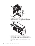
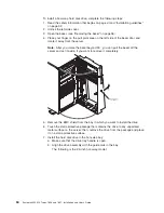
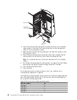
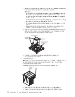
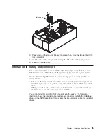

– The 3.5-inch hot-swap SAS and hot-swap SATA models come with the
following to provide signal and power to the 3.5-inch hot-swap SAS/SATA
drives.:
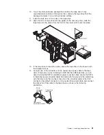
- A single signal cable (thick red and black) that connects to the hard disk
drive backplane and one of the connectors on the SAS/SATA RAID adapter
(see the ServeRAID adapters installation instructions in this document for
more cabling information).
- A single power cable (red/yellow/black) that connects to the
Hard disk
drive backplane power connector
(the power connector labeled A) on the
system board and to the power connector on the hard disk drive backplane.
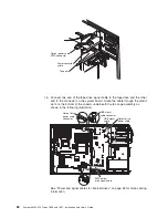
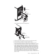
- A single configuration signal cable (black) that connects to the
Hard disk
drive backplane configuration signal connector
(the configuration
connector labeled A) on the system board and the configuration signal
connector on the hard disk drive backplane.
For more information about the requirements for SAS/SATA cables and connecting
SAS/SATA devices, see the documentation that comes with these devices.
For a list of supported options for the server, see http://www.ibm.com/servers/
eserver/serverproven/compat/us/.
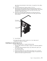
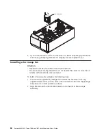
Installing an adapter
The following notes describe the types of adapters that the server supports and
other information that you must consider when installing an adapter. Adapter that
the server supports might vary, depending on your server model.
v
Locate the documentation that comes with the adapter and follow those
instructions in addition to the instructions in this section. If you must change the
switch setting or jumper settings on the adapter, follow the instructions that come
with the adapter.
v
Read the documentation that comes with your operating system.
v
Use PCI slot 2 for video adapters.
v
Do not set the maximum digital video adapter resolution above 1600 x 1200 at
85 Hz for an LCD monitor. This is the highest resolution that is supported for any
add-on video adapter that you install in the server.
v
Any high-definition video-out connector or stereo connector on any add-on video
adapter is not supported
v
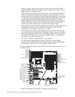
The server provides up to eight adapter connectors, or slots as follows
(depending on your server model):
Note:
The
x8 (x4)
designation for slot 3 (for example) identifies an x8 slot that is
designed to support x8 adapters and x4 adapters that can downshift to operate
at the x4 bandwidth. If you install an x8 adapter in slot 3 that can downshift to
the x4 bandwidth, it will run at the x4 bandwidth. The x8 connector can be used
for x4 and x8 adapters. These same rules apply to the other PCI slots also.
Check the information that comes with your adapter for compatibility information.
– Slots on the system board:
- Slot 1, PCI Express Gen 2 x8 (x8)
- Slot 2, PCI Express Gen 2 x16 (x8)
- Slot 3, PCI Express Gen 2 x8 (x4)
- Slot 4, PCI Express Gen 2 x8 (x4)
- Slot 5, PCI Express Gen 2 x8 (x8)
70
System x3400 M2 Types 7836 and 7837: Installation and User’s Guide
Содержание 783722U
Страница 1: ...System x3400 M2 Types 7836 and 7837 Installation and User s Guide...
Страница 2: ......
Страница 3: ...System x3400 M2 Types 7836 and 7837 Installation and User s Guide...
Страница 8: ...vi System x3400 M2 Types 7836 and 7837 Installation and User s Guide...
Страница 18: ...xvi System x3400 M2 Types 7836 and 7837 Installation and User s Guide...
Страница 57: ...Chapter 2 Installing optional devices 39...
Страница 122: ...104 System x3400 M2 Types 7836 and 7837 Installation and User s Guide...
Страница 153: ......
Страница 154: ...Part Number 69Y4170 Printed in USA 1P P N 69Y4170...


