
v
You have replaced a failed fan as soon as possible.
v
You have replaced a hot-swap fan within 30 seconds of removal.
v
You have replaced a hot-swap drive within 2 minutes of removal.
v
You do not operate the server without the air baffle installed. Operating the
server without the air baffle might cause the microprocessor to overheat.
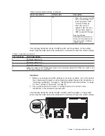
Working inside the server with the power on
Attention:
Static electricity that is released to internal server components when
the server is powered-on might cause the server to halt, which could result in the
loss of data. To avoid this potential problem, always use an electrostatic-discharge
wrist strap or other grounding system when working inside the server with the
power on.
The server (some models) supports hot-swap devices and is designed to operate
safely while it is turned on and the cover is removed. Follow these guidelines when
you work inside a server that is turned on.
v
Avoid wearing loose-fitting clothing on your forearms. Button long-sleeved shirts
before working inside the server; do not wear cuff links while you are working
inside the server.
v
Do not allow your necktie or scarf to hang inside the server.
v
Remove jewelry, such as bracelets, necklaces, rings, and loose-fitting wrist
watches.
v
Remove items from your shirt pocket, such as pens and pencils, that could fall
into the server as you lean over it.
v
Avoid dropping any metallic objects, such as paper clips, hairpins, and screws,
into the server.
Handling static-sensitive devices
Attention:
Static electricity can damage the server and other electronic devices.
To avoid damage, keep static-sensitive devices in their static-protective packages
until you are ready to install them.
To reduce the possibility of electrostatic discharge, observe the following
precautions:
v
Limit your movement. Movement can cause static electricity to build up around
you.
v
The use of a grounding system is recommended. For example, wear an
electrostatic-discharge wrist strap, if one is available. Always use an
electrostatic-discharge wrist strap or other grounding system when working inside
the server with the power on.
v
Handle the device carefully, holding it by its edges or its frame.
v
Do not touch solder joints, pins, or exposed circuitry.
v
Do not leave the device where others can handle and damage it.
v
While the device is still in its static-protective package, touch it to an unpainted
metal surface on the outside of the server for at least 2 seconds. This drains
static electricity from the package and from your body.
v
Remove the device from its package and install it directly into the server without
setting down the device. If it is necessary to set down the device, put it back into
its static-protective package. Do not place the device on the server cover or on a
metal surface.
34
System x3400 M2 Types 7836 and 7837: Installation and User’s Guide
Содержание 783722U
Страница 1: ...System x3400 M2 Types 7836 and 7837 Installation and User s Guide...
Страница 2: ......
Страница 3: ...System x3400 M2 Types 7836 and 7837 Installation and User s Guide...
Страница 8: ...vi System x3400 M2 Types 7836 and 7837 Installation and User s Guide...
Страница 18: ...xvi System x3400 M2 Types 7836 and 7837 Installation and User s Guide...
Страница 57: ...Chapter 2 Installing optional devices 39...
Страница 122: ...104 System x3400 M2 Types 7836 and 7837 Installation and User s Guide...
Страница 153: ......
Страница 154: ...Part Number 69Y4170 Printed in USA 1P P N 69Y4170...