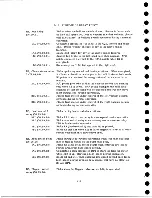
23.0 RELAY CIRCUITS
23.1
LOAD, IN LOW-SPEED REWIND AREA
This is the relay operation sequence for a load operation when less than one-half
inch of tape is wound on the right-hand reel. The machine is in the following condition
before the load-rewind button is depressed,
1.
Both reels are on machine with enough tape threaded across to the right reel
to have the load point reflective spot on that reel.
2.
Full brake on both reels.
3.
48-volt supply available.
4.
Door closed.
5.
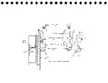
Relays and switches as shown in Figure 35.
When the load-rewind button is depressed, +48 volts is applied to cathode follower
T03J2B (76.08) "Manual Load Rewind." This results in an up level from the cathode
follow er, conditioning the lower leg of AND circuit T03JB30F (76.08). The upper leg
is up because "read status" is up. Therefore, the up level from AND circuit B30F
carries through OR circuit T03JA32F and cathode follow er T03J3B, conditioning relay
driver T03J4B to pick R21. Relay 21 points latch trip relay 15 and 16 to take the tape
drive out of unload status. The tape break light goes out because RIO drops. HD4
picks and starts the vacuum motor running. DPI point changes the power phases to
the take-up motor so that it runs in reverse when DP4 completes the circuit later in
the sequence. Relay 8 completes the circuit to the timer motor and the timer starts.
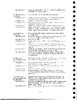
Next in the sequence, the vacuum motor pumps enough air to operate the column
(flapper) switches. The flappers partially seal off the manifold so that enough vacuum
builds up to operate the bellows switch.
The normally open bellows switch points close to pick R l, HD1, HD2, and HD3 at
this time. Relay 1 points change the status of right and left brakes from full brake to
one-half brake. HD1, HD2 and HD3 furnish circuits for all three phases to the m otors
and the reel m otors start.
Next in sequence, the timer switch points open dropping R27. The R 27-2n /c points
furnish a pick curcuitto DP4. DP4 points complete the circuit to the take-up motor which
had previously been conditioned to run in a reverse direction.
The take-up motor starts driving the head down and rotating both reels feeding tape
into the columns. As the tape seals off the columns tightly, the flappers are allowed to
open again. The head-down m icrosw itch operates dropping R2 and R28.
Relay 2AUn/c point completes a circuit to pick DP2. DP2 A and B points close
allowing the capstan drive m otors to start. The capstan-out switches sense that both
capstans are out and drop R3. Dropping relay 3 drops R9; R 9 -3 n /c points close to
pick R27 and 48v to the manual reverse line. Relay 2 7 -ln /o points close to
f48 to the manual start line and the tape is now driven backward.
119
Содержание 727
Страница 6: ......
Страница 67: ...co Q...
Страница 68: ......
Страница 69: ...To Fuse 13 48V...
Страница 70: ......
Страница 71: ......
Страница 72: ......
Страница 73: ...o IC To Fuse 13 48V...
Страница 74: ......
Страница 75: ......
Страница 76: ......
Страница 78: ......
Страница 92: ......
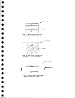
Страница 93: ...039 0035 FIGURE 1 BIT PO SITIO N S O N TAPE CURRENT GENERATOR FIGURE 3c...
Страница 95: ...w PATH OF TAPE THROUGH MACHINE FIGURE 6...
Страница 97: ...SPLIT IDLER ASSEMBLY FIGURE 8...
Страница 98: ......
Страница 99: ...CLUTCH HOUSING POWDERED IRON AND GRAPHITE MIXTURE FIGURE 10 MAGNETIC CLUTCH...
Страница 100: ...PUSH ROD DIAPHRAGM VACUUM COLUMN SWITCHES FIGURE II...
Страница 101: ...BACKWARD MOTOR CAPSTAN MOTOR FORWARD MOTOR...
Страница 102: ...LATCH FIGURE f3...
Страница 103: ...140 140...
Страница 107: ...FIGURE 18 HEAD ASSEMBLY A DJUSTM ENTS...
Страница 108: ...TAPE C LEA N ER FIG URE 19...
Страница 109: ...VACUUM COLUMN ADJUSTMENT FIG U RE 22...
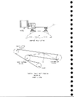
Страница 110: ...DRIVE MOTOR PULLEY CAPSTAN DRIVE BELT TENSION FIGURE 23 REAR VIEW S...
Страница 113: ...CONTROL UNIT TAPE DRIVE TESTER FIGURE 28 TAPE DRIVE TESTER CO NN EC TIO N S...
Страница 116: ...FIGURE 32 HIGH SPEED REWIND...
Страница 129: ...A Capstan Out 13 16 iS i Aftr _ V 1 im m 1 W F B Capstan Retracted FIGURE 33 CAPSTAN DRIVE M O TO R 727 MODEL III...
Страница 130: ...Right Capstan Motor Bottom View Sensing Switch Assy Capstan Out FIGURE 34 CAPSTAN SEN SIN G SW ITCHES 727 MODEL III...
Страница 135: ......
Страница 136: ...v n...
Страница 137: ......
Страница 138: ......
Страница 139: ......
Страница 140: ......
Страница 141: ......
Страница 142: ......
Страница 143: ......
Страница 144: ......
Страница 145: ......
Страница 146: ......
Страница 147: ......
Страница 148: ......
Страница 149: ......
Страница 150: ......
Страница 151: ......
Страница 152: ......
Страница 153: ......
Страница 154: ......
Страница 155: ......
Страница 156: ......
Страница 157: ......
Страница 158: ......
Страница 159: ......
Страница 160: ......
Страница 161: ......
Страница 162: ......
Страница 163: ......

