Bit Switches. These seven switches determine whether ones or zeros are written
in the corresponding tracks when the tape is moving in write status.
G o-Fb. This switch directs the output of the go-backward trigger (T^) in the TDT
either to the go line or the backward line in the tape drive unit.
Manual Forward-Manual R everse. This switch is sim ilar to the customer engi
n e e r^ portable forw ard-reverse switch, and has direct control to move the tape fo r
ward or backward.
Read-W rite. This switch perform s several functions. It sets the status of the
tape drive to either READ ór WRITE. When set to WRITE, it allows the MV (multi
vibrator) to develop write pulses under control of the write frequency dial. When
set to READ, it puts the MV under control of the start-stop frequency dial when the
start-stop switch is turned on, and it sets read status in the tape unit.
Response Select. This dial switch has six wafers. Two select the particular
track to be observed at the read bus or echo bus hubs. A third wafer determines the
logical line that can be observed at the TU response hub. These lines are: select
and rewind, select and at LP, select and TI off, select and TI on, select ready and
read, select ready and write. The last three wafers are used for auto cycle.
Rewind. Depressing this button causes the tape to rewind if the tape unit is
selected and ready.
Start. Depressing this button turns on the go-backward trigger (TR) normally
bringing up the go line. If the go-fb switch is set to forward-backward7 however,
the output of this trigger brings up the backward line.
Start-Stop. This switch is effective only if the read-w rite switch is set to READ.
Turning it on then allows pulses developed by the MV (and gated by "s e le ct, ready
and read") to operate the go-backward trigger through its binary input. Therefore,
if the go-fb switch is set to GO, tape starts and stops at a frequency determined by
the start-stop frequency dial. If the go-fb switch is set to forward-backward, the
forw ard-reverse magnets alternate between forward and reverse.
Stop. Depressing this button turns off the go-backward trigger and thus brings
down the go line, or the backward line, depending on position of the go-fb switch.
Start-Stop Frequency. This dial determines the frequency of starting and stop
ping the tape or of the alternating of the forward reverse magnet as described above,
over a range of about 10 to 150 m s.
TI Set/Reset. This switch directly sets or resets the tape indicator trigger in
the tape drive unit. When the tape indicator is on, neither the go nor the backward
line may be brought up by the tester. "Select and TI on" holds off the go-backward
trigger. When writing on tape the TI com es on and stops the tape motion.
Write Frequency. This dial determines the frequency of the write pulses ini
tiated by the MV over a range of about a 20- to 100-usec period. It should be set
for a period of 67.2 usee using a calibrated scope.
80
Содержание 727
Страница 6: ......
Страница 67: ...co Q...
Страница 68: ......
Страница 69: ...To Fuse 13 48V...
Страница 70: ......
Страница 71: ......
Страница 72: ......
Страница 73: ...o IC To Fuse 13 48V...
Страница 74: ......
Страница 75: ......
Страница 76: ......
Страница 78: ......
Страница 92: ......
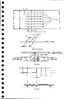
Страница 93: ...039 0035 FIGURE 1 BIT PO SITIO N S O N TAPE CURRENT GENERATOR FIGURE 3c...
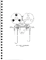
Страница 95: ...w PATH OF TAPE THROUGH MACHINE FIGURE 6...
Страница 97: ...SPLIT IDLER ASSEMBLY FIGURE 8...
Страница 98: ......
Страница 99: ...CLUTCH HOUSING POWDERED IRON AND GRAPHITE MIXTURE FIGURE 10 MAGNETIC CLUTCH...
Страница 100: ...PUSH ROD DIAPHRAGM VACUUM COLUMN SWITCHES FIGURE II...
Страница 101: ...BACKWARD MOTOR CAPSTAN MOTOR FORWARD MOTOR...
Страница 102: ...LATCH FIGURE f3...
Страница 103: ...140 140...
Страница 107: ...FIGURE 18 HEAD ASSEMBLY A DJUSTM ENTS...
Страница 108: ...TAPE C LEA N ER FIG URE 19...
Страница 109: ...VACUUM COLUMN ADJUSTMENT FIG U RE 22...
Страница 110: ...DRIVE MOTOR PULLEY CAPSTAN DRIVE BELT TENSION FIGURE 23 REAR VIEW S...
Страница 113: ...CONTROL UNIT TAPE DRIVE TESTER FIGURE 28 TAPE DRIVE TESTER CO NN EC TIO N S...
Страница 116: ...FIGURE 32 HIGH SPEED REWIND...
Страница 129: ...A Capstan Out 13 16 iS i Aftr _ V 1 im m 1 W F B Capstan Retracted FIGURE 33 CAPSTAN DRIVE M O TO R 727 MODEL III...
Страница 130: ...Right Capstan Motor Bottom View Sensing Switch Assy Capstan Out FIGURE 34 CAPSTAN SEN SIN G SW ITCHES 727 MODEL III...
Страница 135: ......
Страница 136: ...v n...
Страница 137: ......
Страница 138: ......
Страница 139: ......
Страница 140: ......
Страница 141: ......
Страница 142: ......
Страница 143: ......
Страница 144: ......
Страница 145: ......
Страница 146: ......
Страница 147: ......
Страница 148: ......
Страница 149: ......
Страница 150: ......
Страница 151: ......
Страница 152: ......
Страница 153: ......
Страница 154: ......
Страница 155: ......
Страница 156: ......
Страница 157: ......
Страница 158: ......
Страница 159: ......
Страница 160: ......
Страница 161: ......
Страница 162: ......
Страница 163: ......


