R8, Head cover not
down (09. 05)
8AU (09.06) N/C
N/O
8BU (09.05)
8BL (09.02)
R9, 10, Tape out of
columns (09. 05)
9, 10AU (09.05)
9, 10AL (09.04)
9, 10BU (09.05)
N/C
N/O
9, 10BL (09.02)
R l l , 22, Unload (09.05)
11AU (09. 05)
U A L (09. 04)
11BU (09.06)
11BL (09.06)
22-1 (09.01)
22-2 (09.01)
22-3 (09.02)
22-4 (09.02) N/C
22-5 (09.02)
Pick R8 when the head cover is not all the way down. Hold
it until the head cover is all the way down and tape is in both
columns.
This runs the capstan motor only when using the capstans
or when moving the capstans in or out.
This allows the capstans to extend (drop HD8) during load
rewind when the head cover is all the way down and tape is
in both columns.
When lowering tape into the columns during load-rewind,
stop the take-up motor when the holding conditions on R8
are satisfied.
This allows R34-1 to have complete control of the manual
start line when the head cover gets down and tape gets in
both columns.
R9 is controlled by the left column microswitch; R10, by
the right. When vacuum is up, these relays are picked only
when tape is out of their respective columns.
These insure that tape is out of both columns before: (a)stop
ping the vacuum motor when unloading (LP R26), (b) starting
the rewind motor for high-speed rewind (DP3, R12).
They drop the run relays if tape should break during any opera
tion where tape is being moved by the drive capstans.
These prevent braking the left reel while slowing down from
a high speed rewind.
These hold R8 until tape gets in both columns.
These drop the manual stop line when tape gets into either
column. This occu rs during load rewind when tape is being
low ered. It insures that tape will get into both columns.
This is picked when R21, unload is up.
When the head cover is up and tape is out of both colum ns,
one of two possible conditions exists: (a) unload is completed,
(b) it is ready to start high speed m otor, if R l l is picked,
the unload button has been pressed, so example (a) applies.
While unloading, keep the run relays up until the operation
is completed.
Pick R13. (See R13.)
Retract the capstans when an unload operation has been
started.
Place all three photo lights in series with R14 while un
loaded. Thus in order to start a load rewind operation from
an unloaded status, all three photo lights must be conducting,
i. e . , R14 must be picked.
This is protection in case the read-w rite status trigger
filament should burn out. While unloaded, and while unload
ing, the write heads and erase heads cannot conduct.
Put the moving coil in a start status when unloaded for ease
in changing re e ls.
Drop R33 and R34 to stop tape in case the unload button is
pressed while the machine is rewinding at low speed.
Drop the load point relay.
87
Содержание 727
Страница 6: ......
Страница 67: ...co Q...
Страница 68: ......
Страница 69: ...To Fuse 13 48V...
Страница 70: ......
Страница 71: ......
Страница 72: ......
Страница 73: ...o IC To Fuse 13 48V...
Страница 74: ......
Страница 75: ......
Страница 76: ......
Страница 78: ......
Страница 92: ......
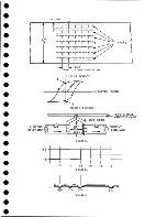
Страница 93: ...039 0035 FIGURE 1 BIT PO SITIO N S O N TAPE CURRENT GENERATOR FIGURE 3c...
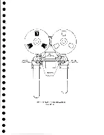
Страница 95: ...w PATH OF TAPE THROUGH MACHINE FIGURE 6...
Страница 97: ...SPLIT IDLER ASSEMBLY FIGURE 8...
Страница 98: ......
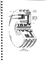
Страница 99: ...CLUTCH HOUSING POWDERED IRON AND GRAPHITE MIXTURE FIGURE 10 MAGNETIC CLUTCH...
Страница 100: ...PUSH ROD DIAPHRAGM VACUUM COLUMN SWITCHES FIGURE II...
Страница 101: ...BACKWARD MOTOR CAPSTAN MOTOR FORWARD MOTOR...
Страница 102: ...LATCH FIGURE f3...
Страница 103: ...140 140...
Страница 107: ...FIGURE 18 HEAD ASSEMBLY A DJUSTM ENTS...
Страница 108: ...TAPE C LEA N ER FIG URE 19...
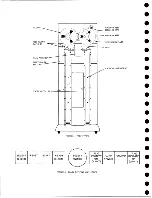
Страница 109: ...VACUUM COLUMN ADJUSTMENT FIG U RE 22...
Страница 110: ...DRIVE MOTOR PULLEY CAPSTAN DRIVE BELT TENSION FIGURE 23 REAR VIEW S...
Страница 113: ...CONTROL UNIT TAPE DRIVE TESTER FIGURE 28 TAPE DRIVE TESTER CO NN EC TIO N S...
Страница 116: ...FIGURE 32 HIGH SPEED REWIND...
Страница 129: ...A Capstan Out 13 16 iS i Aftr _ V 1 im m 1 W F B Capstan Retracted FIGURE 33 CAPSTAN DRIVE M O TO R 727 MODEL III...
Страница 130: ...Right Capstan Motor Bottom View Sensing Switch Assy Capstan Out FIGURE 34 CAPSTAN SEN SIN G SW ITCHES 727 MODEL III...
Страница 135: ......
Страница 136: ...v n...
Страница 137: ......
Страница 138: ......
Страница 139: ......
Страница 140: ......
Страница 141: ......
Страница 142: ......
Страница 143: ......
Страница 144: ......
Страница 145: ......
Страница 146: ......
Страница 147: ......
Страница 148: ......
Страница 149: ......
Страница 150: ......
Страница 151: ......
Страница 152: ......
Страница 153: ......
Страница 154: ......
Страница 155: ......
Страница 156: ......
Страница 157: ......
Страница 158: ......
Страница 159: ......
Страница 160: ......
Страница 161: ......
Страница 162: ......
Страница 163: ......


