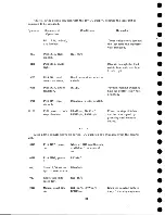
Conditions
Remarks
Systems
Sequence of
Operation
75.10. Q1
Full power to both
R4 pts.
stop clutches.
04C
Drop R2, rewind.
"Caps out" m icroswitches
Both capstans are fully
extended.
05C
Drop R3, R31, r e
wind.
R2BL
04D
Drop R5, R6,
start slow rewind,
and HD 7, time
delay.
R2AU
75.10.02
Stop time delay
mtr.
HD7 pt.
Time delay arm returns
to home position.
06H
Drop R13, clutch
transfer.
R3BU
Vacuum column switches
now control reel clutches
(75.10.01). These
switches keep tape in the
center third of each co l
umn from now on.
06B
Drop retracting
solenoid latch.
R6AL
011
Pick R33, r e
verse.
R 31-2n /c
02J
Manual reverse
line com es up.
R33-2
Energize the reverse
magnet. De-energize
the forward magnet.
O il
Pick R34, start.
R33-1
02E
Manual start line
com es up.
R34-1
Energize moving coil in
the start direction.
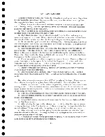
Tape moves in the reverse direction until the load point is sensed at the load-
point photo cell. As the tape passes under the load-point photo cell, the light is r e
flected to the cell. The cell output is a negative shift and is applied to an inverter
(75. 04). The output of this inverter is again inverted and pulls over a 20 ms SSrp.
The left output of this SST , nnot arriving at load point" goes down, dropping the
lower leg of AND circuit F27 (75. 05. 01). This puts the moving coil in the stop posi
tion and stops the tape with a reverse-stop status. At this same time, the right
28
Содержание 727
Страница 6: ......
Страница 67: ...co Q...
Страница 68: ......
Страница 69: ...To Fuse 13 48V...
Страница 70: ......
Страница 71: ......
Страница 72: ......
Страница 73: ...o IC To Fuse 13 48V...
Страница 74: ......
Страница 75: ......
Страница 76: ......
Страница 78: ......
Страница 92: ......
Страница 93: ...039 0035 FIGURE 1 BIT PO SITIO N S O N TAPE CURRENT GENERATOR FIGURE 3c...
Страница 95: ...w PATH OF TAPE THROUGH MACHINE FIGURE 6...
Страница 97: ...SPLIT IDLER ASSEMBLY FIGURE 8...
Страница 98: ......
Страница 99: ...CLUTCH HOUSING POWDERED IRON AND GRAPHITE MIXTURE FIGURE 10 MAGNETIC CLUTCH...
Страница 100: ...PUSH ROD DIAPHRAGM VACUUM COLUMN SWITCHES FIGURE II...
Страница 101: ...BACKWARD MOTOR CAPSTAN MOTOR FORWARD MOTOR...
Страница 102: ...LATCH FIGURE f3...
Страница 103: ...140 140...
Страница 107: ...FIGURE 18 HEAD ASSEMBLY A DJUSTM ENTS...
Страница 108: ...TAPE C LEA N ER FIG URE 19...
Страница 109: ...VACUUM COLUMN ADJUSTMENT FIG U RE 22...
Страница 110: ...DRIVE MOTOR PULLEY CAPSTAN DRIVE BELT TENSION FIGURE 23 REAR VIEW S...
Страница 113: ...CONTROL UNIT TAPE DRIVE TESTER FIGURE 28 TAPE DRIVE TESTER CO NN EC TIO N S...
Страница 116: ...FIGURE 32 HIGH SPEED REWIND...
Страница 129: ...A Capstan Out 13 16 iS i Aftr _ V 1 im m 1 W F B Capstan Retracted FIGURE 33 CAPSTAN DRIVE M O TO R 727 MODEL III...
Страница 130: ...Right Capstan Motor Bottom View Sensing Switch Assy Capstan Out FIGURE 34 CAPSTAN SEN SIN G SW ITCHES 727 MODEL III...
Страница 135: ......
Страница 136: ...v n...
Страница 137: ......
Страница 138: ......
Страница 139: ......
Страница 140: ......
Страница 141: ......
Страница 142: ......
Страница 143: ......
Страница 144: ......
Страница 145: ......
Страница 146: ......
Страница 147: ......
Страница 148: ......
Страница 149: ......
Страница 150: ......
Страница 151: ......
Страница 152: ......
Страница 153: ......
Страница 154: ......
Страница 155: ......
Страница 156: ......
Страница 157: ......
Страница 158: ......
Страница 159: ......
Страница 160: ......
Страница 161: ......
Страница 162: ......
Страница 163: ......


