7. 0
LOAD-REWIND OPERATION
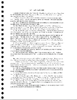
Initiate a load-rewind operation by pressing the load-rewind button. Doing this
always has the same end result; the tape is moved until the load point stops beneath
the load-point photo cell.
In this discussion of a load-rewind operation, assume the following initial
conditions:
1. The power cable is connected to a control unit as a source of power. The
power is turned off.
2. The tape drive unit is unloaded (the normal condition with power off); the cap
stans are latched in and the head cover is up.
3. No reels of tape are on the machine.
The following is a word sequence of bringing up power and load rewinding.
Step 1. Turn on power in the unit controlling the tape drive. Doing this supplies
AC power to the tape drive, which starts filaments, blowers, fan, and 48v DC supply.
Step 20 After a five-minute warm up period, DC supplies to the tape drive come
up. A npower on" relay picks to indicate the presence of these supplies. The ma
chine can now be operated.
Step 3. Mount the full reel of tape on the file reel, and thread the tape past the
the idlers and read-write head assembly over to the machine reel. The reel brakes
may be released by pressing the buttons below the file reel. Wind several turns of
the tape manually on the machine reel until the load point is well to the right of the
head assembly. Close the reel door and press the load-rewind button.
Step 4. The vacuum motor and tim e-delay motor start turning.
Step 5. At the end of the time delay (about five seconds) the vacuum is at opera
ting strength. The take-up motor starts turning in a reverse direction, lowering the
head cover assembly and lowering the tape into each column.
Step 6. When three conditions are satisfied, the take-up motor is turned off.
These three conditions are: (1) the head cover is all the way down, (2) tape is in the
right column, and (3) tape is in the left column. The drive capstans start turning
and are extended.
Step 7. When the "capstan out" m icroswitches indicate that both capstans are
fully extended, the machine goes into a reverse-start status, and tape moves in a
reverse direction until the load point is sensed. When the start button is pressed,
the machine is ready for useQ
The following is the actual relay operation for load-rewind. The sequence chart
and the wiring diagram (section 18. 0) can be used with this description. Locations
of relays are denoted by the system diagram page number and the corresponding
letter in the wiring diagram.
7.1 INITIAL CONDITIONS
When external power is first turned on, the 48v DC supply is energized from
phases 1 and 2 of the 30, 208v, AC supply, and the blower and fan motor are ener
gized from phases 2 and 3 (75010. 02). Filament power is applied through the fila
ment transform er (75.10.05) from the 236v regulated external supply.
23
Содержание 727
Страница 6: ......
Страница 67: ...co Q...
Страница 68: ......
Страница 69: ...To Fuse 13 48V...
Страница 70: ......
Страница 71: ......
Страница 72: ......
Страница 73: ...o IC To Fuse 13 48V...
Страница 74: ......
Страница 75: ......
Страница 76: ......
Страница 78: ......
Страница 92: ......
Страница 93: ...039 0035 FIGURE 1 BIT PO SITIO N S O N TAPE CURRENT GENERATOR FIGURE 3c...
Страница 95: ...w PATH OF TAPE THROUGH MACHINE FIGURE 6...
Страница 97: ...SPLIT IDLER ASSEMBLY FIGURE 8...
Страница 98: ......
Страница 99: ...CLUTCH HOUSING POWDERED IRON AND GRAPHITE MIXTURE FIGURE 10 MAGNETIC CLUTCH...
Страница 100: ...PUSH ROD DIAPHRAGM VACUUM COLUMN SWITCHES FIGURE II...
Страница 101: ...BACKWARD MOTOR CAPSTAN MOTOR FORWARD MOTOR...
Страница 102: ...LATCH FIGURE f3...
Страница 103: ...140 140...
Страница 107: ...FIGURE 18 HEAD ASSEMBLY A DJUSTM ENTS...
Страница 108: ...TAPE C LEA N ER FIG URE 19...
Страница 109: ...VACUUM COLUMN ADJUSTMENT FIG U RE 22...
Страница 110: ...DRIVE MOTOR PULLEY CAPSTAN DRIVE BELT TENSION FIGURE 23 REAR VIEW S...
Страница 113: ...CONTROL UNIT TAPE DRIVE TESTER FIGURE 28 TAPE DRIVE TESTER CO NN EC TIO N S...
Страница 116: ...FIGURE 32 HIGH SPEED REWIND...
Страница 129: ...A Capstan Out 13 16 iS i Aftr _ V 1 im m 1 W F B Capstan Retracted FIGURE 33 CAPSTAN DRIVE M O TO R 727 MODEL III...
Страница 130: ...Right Capstan Motor Bottom View Sensing Switch Assy Capstan Out FIGURE 34 CAPSTAN SEN SIN G SW ITCHES 727 MODEL III...
Страница 135: ......
Страница 136: ...v n...
Страница 137: ......
Страница 138: ......
Страница 139: ......
Страница 140: ......
Страница 141: ......
Страница 142: ......
Страница 143: ......
Страница 144: ......
Страница 145: ......
Страница 146: ......
Страница 147: ......
Страница 148: ......
Страница 149: ......
Страница 150: ......
Страница 151: ......
Страница 152: ......
Страница 153: ......
Страница 154: ......
Страница 155: ......
Страница 156: ......
Страница 157: ......
Страница 158: ......
Страница 159: ......
Страница 160: ......
Страница 161: ......
Страница 162: ......
Страница 163: ......


