leg of AND circuit T03JC3F (76.08). Select and ready conditions the lower leg.
The resulting up level conditions the relay driver T03J4B; R21 is picked. If R21
is picked when less than one-half inch of tape is on the right reel, a slow-speed
rewind operation results (Figure 36). Picking R21 with m ore than one-half inch
of tape on the right reel causes a high-speed rewind operation (Figure 37).
23.4 HIGH-SPEED REWIND
This operation starts with the tape drive in the following condition. Enough
tape is wound on the right-hand reel to operate the arm switch; the drive is in a
stop statuso When the load-rewind button is depressed, relays 2, 9, 12, 21, and
28 pick up. DP2 drops, breaking the circuit to the capstan drive m otors. DP3
starts the rewind motor when the capstans are retracted, the head is up, and tape
is out of the columns. Tape is wound from the right-hand reel to the left-hand
reel at high speed until the art switch makes. At this time DP3 drops the circuit
to the rewind motor and one-half brake is applied to the right-hand reel. Relay 8
starts the timer m otor; five seconds later the timer points transfer. This delay
period allows the reels to coast to a stop. After the reels have stopped, the head
com es back down, tape enters the columns, the capstans come out and tape is
driven backward to the load point.
23.5
UNLOAD
Starting with tape setting at load point, depressing the unload button results
in the following sequence (Figure 38). The unload button latch picks R15 and R15-2
n /o closes to pick RIO. Relays 2 and 28 are picked. Relay 2AUn/c transfers,
dropping DP2 which opens the circuit to the capstan drive motors so that the cap
stans retract. Relay 2 points also cause one-half brake to be applied to both the
right- and left-hand reels.
The capstan in microswitches operate when the capstans are fully retracted,
causing R27 to be picked. Relay 2 7 -ln /o closes to bring up TTmanual startM
and
this up level AND’ s with "At Load Point" in AND circuit T04JG20F (76. 04). The
resulting up level conditions relay driver T04J5B, causing R26 to be picked.
Relay 2 6 -ln /o closes and completes a circuit to the R25 latch trip coil. Relay
25-4n/o opens dropping the "At L .P ." to AND circuit T04JG20F and the resulting
down level allows R26 to fall.
DP4 also picks as a result of the capstan-in switches’ closing. Therefore,
the take-up motor starts to bring up the read-write head. As the head-up m icro
switch senses that the head is fully raised and the flappers move to operate the
column switches, R16 (unload stop) is latch picked. HD4 falls as a result of
the transfer of R 1 6 -ln /o ; the HD4 points break the circuit to the vacuum m otor.
Vacuum falls. Then the bellows switch senses loss of vacuum and its points trans
fer allowing HD1, 2, 3, and R1 to drop. Relay 1 points effect a change from half
brake to full brake and the drive now sets in an unloaded condition.
121
Содержание 727
Страница 6: ......
Страница 67: ...co Q...
Страница 68: ......
Страница 69: ...To Fuse 13 48V...
Страница 70: ......
Страница 71: ......
Страница 72: ......
Страница 73: ...o IC To Fuse 13 48V...
Страница 74: ......
Страница 75: ......
Страница 76: ......
Страница 78: ......
Страница 92: ......
Страница 93: ...039 0035 FIGURE 1 BIT PO SITIO N S O N TAPE CURRENT GENERATOR FIGURE 3c...
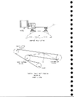
Страница 95: ...w PATH OF TAPE THROUGH MACHINE FIGURE 6...
Страница 97: ...SPLIT IDLER ASSEMBLY FIGURE 8...
Страница 98: ......
Страница 99: ...CLUTCH HOUSING POWDERED IRON AND GRAPHITE MIXTURE FIGURE 10 MAGNETIC CLUTCH...
Страница 100: ...PUSH ROD DIAPHRAGM VACUUM COLUMN SWITCHES FIGURE II...
Страница 101: ...BACKWARD MOTOR CAPSTAN MOTOR FORWARD MOTOR...
Страница 102: ...LATCH FIGURE f3...
Страница 103: ...140 140...
Страница 107: ...FIGURE 18 HEAD ASSEMBLY A DJUSTM ENTS...
Страница 108: ...TAPE C LEA N ER FIG URE 19...
Страница 109: ...VACUUM COLUMN ADJUSTMENT FIG U RE 22...
Страница 110: ...DRIVE MOTOR PULLEY CAPSTAN DRIVE BELT TENSION FIGURE 23 REAR VIEW S...
Страница 113: ...CONTROL UNIT TAPE DRIVE TESTER FIGURE 28 TAPE DRIVE TESTER CO NN EC TIO N S...
Страница 116: ...FIGURE 32 HIGH SPEED REWIND...
Страница 129: ...A Capstan Out 13 16 iS i Aftr _ V 1 im m 1 W F B Capstan Retracted FIGURE 33 CAPSTAN DRIVE M O TO R 727 MODEL III...
Страница 130: ...Right Capstan Motor Bottom View Sensing Switch Assy Capstan Out FIGURE 34 CAPSTAN SEN SIN G SW ITCHES 727 MODEL III...
Страница 135: ......
Страница 136: ...v n...
Страница 137: ......
Страница 138: ......
Страница 139: ......
Страница 140: ......
Страница 141: ......
Страница 142: ......
Страница 143: ......
Страница 144: ......
Страница 145: ......
Страница 146: ......
Страница 147: ......
Страница 148: ......
Страница 149: ......
Страница 150: ......
Страница 151: ......
Страница 152: ......
Страница 153: ......
Страница 154: ......
Страница 155: ......
Страница 156: ......
Страница 157: ......
Страница 158: ......
Страница 159: ......
Страница 160: ......
Страница 161: ......
Страница 162: ......
Страница 163: ......

