background image

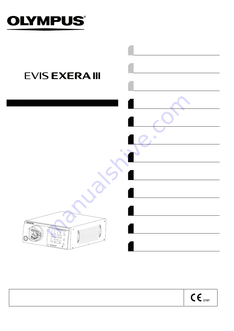
INSTRUCTIONS

EVIS EXERA III XENON LIGHT SOURCE

OLYMPUS CLV-190

Labels and Symbols

1

Important Information — Please Read Before 
Use

3

Summary of the Equipment Functions

12

Chapter 1 Checking the Package Contents

15

Chapter 2 Nomenclature and Functions

17

Chapter 3 Installation and Connection

27

Chapter 4 Inspection

41

Chapter 5 Operation

65

Chapter 6 Lamp Replacement

81

Chapter 7 Reprocessing, Storage, 

Disposal, and Transportation

93

Chapter 8 Troubleshooting

103

Appendix

109

USA: CAUTION:

Federal law restricts this device to sale by or on the order of a physician.

Содержание EVIS EXERA III

Страница 1: ...ecking the Package Contents 15 Chapter 2 Nomenclature and Functions 17 Chapter 3 Installation and Connection 27 Chapter 4 Inspection 41 Chapter 5 Operation 65 Chapter 6 Lamp Replacement 81 Chapter 7 R...

Страница 2: ......

Страница 3: ...list 15 Chapter 2 Nomenclature and Functions 17 2 1 Nomenclature and functions 17 2 2 Front panel 19 2 3 Rear and side panels 24 Chapter 3 Installation and Connection 27 3 1 Precautions for installat...

Страница 4: ...the transillumination function 58 4 12 Inspection of the high intensity mode 59 4 13 Inspection of air and water feeding 62 4 14 After inspection 64 Chapter 5 Operation 65 5 1 Attention to operation...

Страница 5: ...essing 97 Equipment needed 97 7 5 Reprocessing the light source and accessories 98 7 6 Storage 101 7 7 Disposal 101 7 8 Transportation 101 Chapter 8 Troubleshooting 103 8 1 Troubleshooting 103 8 2 Tro...

Страница 6: ...iv Contents CLV 190 INSTRUCTION MANUAL...

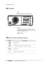
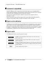
Страница 7: ...ng Serial number Manufacturer name Crossed out wheeled bin symbol Indicates to see the instruction manual for the cable to be connected Cautions that the inside is extremely hot immediately after the...

Страница 8: ...n Manufacturer Authorized representative in the European Community Translation Importer into European Union Dry the endoscope connector before insertion The UDI label is required by some countries reg...

Страница 9: ...re greater than its risks Fully explain to the patient the potential benefits and risks of the endoscopy and endoscopic treatment as well as any examination treatment methods that can be performed in...

Страница 10: ...ion transformer The isolation transformer is a safety device that is used to isolate noninsulated equipment with potentially high leakage currents to decrease the possibility of electric shock Automat...

Страница 11: ...re defined by the hospital s medical administrators or other official institutions such as academic societies on endoscopy follow those standards If there are no official qualification standards the o...

Страница 12: ...ssemble modify or attempt to repair it patient or user injury equipment damage and or the impossibility to obtain the expected functionality can result Some problems that appear to be malfunctions may...

Страница 13: ...t source in the following locations An explosion or fire may result because this video system center is not explosion proof The concentration of oxygen is high Oxidizing agents such as nitrous oxide N...

Страница 14: ...ight source irradiates strong examination light the disconnected end of the light guide cable or the distal end of the endoscope becomes very hot To prevent a fire hazard do not bring the distal end o...

Страница 15: ...to press the buttons on the front panel This may damage the buttons Do not touch the electrical contacts inside the light source s connectors Do not simultaneously touch any of the exposed electrical...

Страница 16: ...the instrument can safely be applied to any organ except the heart The part of the body that an endoscope or electrosurgical accessory can safely be applied to depends on the classification of the equ...

Страница 17: ...or seriously affect the cardiac function of the patient As specified by the international standard IEC 60601 1 any applied part used for observation or treatment of the heart or areas near the heart m...

Страница 18: ...utomatically When the light source is used in combination with a fiber endoscope the examination light intensity has to be adjusted manually Section 5 5 Brightness adjustment Optical digital observati...

Страница 19: ...nation lamp The lamp usage indicator on the front panel of the light source displays the total accumulated operation hours of the examination lamp to indicate the time for replacement Section 4 6 Chec...

Страница 20: ...14 Summary of the Equipment Functions CLV 190 INSTRUCTION MANUAL...

Страница 21: ...damage If the light source is damaged a component is missing or you have any questions do not use the light source and immediately contact Olympus 1 1 Checking the package contents list Light source E...

Страница 22: ...16 1 1 Checking the package contents list CLV 190 INSTRUCTION MANUAL Ch 1...

Страница 23: ...Description Power ON OFF Brightness Decrease brightness Increase brightness Exchange lamp Lamp usage indicator Lamp usage indicator reset New lamp Lamp usage indicator Emergency lamp Examination lamp...

Страница 24: ...and functions CLV 190 INSTRUCTION MANUAL Ch 2 Rear and side panels Symbol Description Symbol Description Refer to instructions Warns that the lamp is hot Serial number Potential equalization terminal...

Страница 25: ...on 1 Power switch Press to turn the light source ON or OFF 2 Power indicator Lights up when the light source is ON 3 Output socket Connects the endoscope or the light guide cable to this socket This s...

Страница 26: ...20 2 2 Front panel CLV 190 INSTRUCTION MANUAL Ch 2 Control panel buttons 13 9 8 7 6 5 14 12 11 10...

Страница 27: ...n Press to turn ON the examination lamp Press for a longer period while the lamp is ON to turn it OFF Section 5 3 Turning the light source ON and igniting the examination lamp Section 5 10 Extinguishi...

Страница 28: ...22 2 2 Front panel CLV 190 INSTRUCTION MANUAL Ch 2 Control panel indicators 15 18 16 26 25 23 17 22 24 20 21 19...

Страница 29: ...mode available with the connected endoscope Section 5 6 Optical digital observation 20 Lamp indicators These indicators display whether the examination lamp xenon lamp lights up ON or not STBY Sectio...

Страница 30: ...24 2 3 Rear and side panels CLV 190 INSTRUCTION MANUAL Ch 2 Rear panel Side panel 2 3 Rear and side panels 7 3 1 9 8 2 5 4 6 11 10 12...

Страница 31: ...tential equalization terminal This terminal is connected to a potential equalization terminal of the other equipment connected to the light source The electrical potential of the equipment are equaliz...

Страница 32: ...26 2 3 Rear and side panels CLV 190 INSTRUCTION MANUAL Ch 2...

Страница 33: ...all system components before connecting them Otherwise equipment damage or malfunction can result Use appropriate cables only Otherwise equipment damage or malfunction can result Properly and securel...

Страница 34: ...bile workstation or another stable location Section 3 3 on page 29 2 Install the water container Only if air water feeding function is used Section 3 4 on page 33 3 Select the lamp ignition mode Secti...

Страница 35: ...AJ 1205 Otherwise the light source may topple down or drop and operator or patient injury may occur or equipment damage can result When using the mobile workstation confirm that excessive force is not...

Страница 36: ...as shown in Figure 3 1 Figure 3 1 2 According to the combination of equipment install the shelf of the mobile workstation as described in the mobile workstation s instruction manual 3 For WM NP2 WM DP...

Страница 37: ...the back of the two foot holders of the light source Place the foot holders to the two corresponding positions on the rear and attach them lightly See Figure 3 3 NOTE If the light source is placed on...

Страница 38: ...the foot holders and lightly attach the foot holders to the sheet Figure 3 4 2 Place the light source on the pattern sheet and check that the feet fit into the foot holders 3 Remove the light source...

Страница 39: ...water container at the water container holder on the left side of the light source Figure 3 5 3 5 Selection of the lamp ignition mode Either manual or auto ignition mode can be selected to ignite the...

Страница 40: ...CTION MANUAL Ch 3 Manual ignition MANU Automatic ignition AUTO Set the lamp ignition mode switch on the rear panel to MANU Figure 3 6 Set the lamp ignition mode switch on the rear panel to AUTO Figure...

Страница 41: ...video system center Connect the video system center CV 190 to the light source using the cables listed below Model Product name MAJ 1933 Digital light source cable MAJ 1941 Light source cable CV 190 C...

Страница 42: ...LV 190 INSTRUCTION MANUAL Ch 3 Table 3 2 Figure 3 9 Connect the video system center CV S190 to the light source using the cables listed below Model Product name MAJ 1941 Light source cable OTV S190 CL...

Страница 43: ...3 6 Connection of the video system center 37 CLV 190 INSTRUCTION MANUAL Ch 3 CAUTION Bring the connected image cable into line with the rear panels as shown in Figure 3 10 Figure 3 10...

Страница 44: ...enter is ON the function of the foot switch depends on the setting of the video system center Two foot switches can be used if they are connected to the video system center and light source respective...

Страница 45: ...If the capacity is insufficient a fire can result or the circuit breaker may trip and it may turn OFF not only the light source but also all other equipment connected to the same power circuit When us...

Страница 46: ...y vary from this drawing as in each country the commercialized cable is in accordance to the local applicable norm 1 Confirm that the power switch is not pressed in 2 Connect the power cord to the AC...

Страница 47: ...e observed do not use the light source and see Chapter 8 Troubleshooting If the light source with any irregularity is used the light source may malfunction or be damaged and an electric shock and or b...

Страница 48: ...of the examination lamp Section 4 6 on page 48 5 Confirm that the examination lamp turns ON OFF normally Section 4 7 on page 48 6 Check the brightness mode Section 4 8 on page 50 7 Inspect the necessa...

Страница 49: ...isconnected end of the light guide cable or distal end of the endoscope in contact with a flammable object such as operating room drapes when the examination lamp is turned ON Do not touch the distal...

Страница 50: ...e cable may cause operator and or patient injury or a fire by igniting flammable material such as an operating room drape 1 Inspect the light guide cable and rigid endoscope as described in the endosc...

Страница 51: ...ope s instruction manual 2 Insert the endoscope connector or light guide connector into the output socket on the front panel of the light source until it clicks Figure 4 2 3 Connect the videoscope cab...

Страница 52: ...rm that the ventilation grills on the side and rear panels of the light source are not covered with dust or other materials 2 Confirm that the lamp cover is attached firmly Figure 4 3 NOTE For safety...

Страница 53: ...till lights up replace the examination lamp with a new one as described in Section 6 1 Replacement of the examination xenon lamp If after following the steps above the emergency lamp indicator continu...

Страница 54: ...stal end of the light guide cable or the output socket of the light source when they are emitting light The intense light may cause eye injury 4 6 Checking the lamp usage indicator Check the lamp usag...

Страница 55: ...lamp indicator ON lights up Figure 4 5 2 Confirm that the emergency lamp indicator on the control panel is not lighting or blinking See Figure 4 5 3 Confirm that the examination light is emitted from...

Страница 56: ...he brightness mode to MANU Setting it to AUTO does not enable the automatic brightness adjustment and the brightness may not be adequate 4 8 Inspection of the brightness mode selection function 1 Conf...

Страница 57: ...ent Confirm that the brightness of the examination lamp can be adjusted The inspection method differs according to the endoscope to be used Select either the AUTO or MANU mode as shown in Table 4 1 Br...

Страница 58: ...ustment does not function and the brightness may be insufficient 2 Press the lamp button on the control panel the examination lamp is ignited Figure 4 8 3 Press the brightness mode button and select A...

Страница 59: ...peration 5 Hold the distal end of the endoscope at a distance between 30 and 40 mm to the object and press the brightness buttons or Confirm the following Each time either of the brightness buttons is...

Страница 60: ...ment always set the brightness to the minimum level necessary to complete the examination If the light is too bright eye injury or burns can result 1 Press the lamp button on the control panel the exa...

Страница 61: ...cation on the light source varies in an interlocked operation 3 Press the brightness buttons or and confirm the following Each time either of the brightness buttons is pressed a beep is heard and the...

Страница 62: ...1 Confirm that the available observation mode indicators show the available optical digital observation modes Figure 4 14 NOTE The available observation modes vary depending on the connected endoscop...

Страница 63: ...at the moment it is turned ON 3 If more than one available observation mode indicator lights up press the observation mode select button and confirm that each press switches the optical digital observ...

Страница 64: ...looking into the eyepiece of the endoscope The light intensity may cause eye injury NOTE The transillumination function is not available when no endoscope is connected to the light source or the exam...

Страница 65: ...t source may also be compatible for use in combination with the light source For further details refer to the instruction manual for the endoscope or the light guide cable to be used or contact Olympu...

Страница 66: ...he intensity mode button on the control panel the normal mode is changed to the high intensity mode Figure 4 21 4 Confirm that the high intensity mode indicator lights up and that the light emitted fr...

Страница 67: ...ll lighting up 9 Turn the light source OFF and turn it ON again Confirm that the high intensity mode indicator lights up 10 Connect the endoscope that is compatible with the high intensity mode to the...

Страница 68: ...irflow indicator ON lights up 2 Press the airflow regulator button repeatedly and confirm that the indication of the airflow regulator indicators light up in the cycle of L low M medium and H high Fig...

Страница 69: ...scope 8 Remove the distal end of the endoscope from the sterile water 9 Depress the air water valve of the endoscope 10 Press the airflow regulator button to change the airflow level setting and confi...

Страница 70: ...RUCTION MANUAL Ch 4 4 14 After inspection If the light source will not be used immediately press the power switch on the light source to turn it OFF refer to Section 5 11 Turning the light source OFF...

Страница 71: ...operation of the light source Before using the light source make sure to perform inspection of the light source as described in Chapter 4 Inspection WARNING Be sure to wear protective equipment such a...

Страница 72: ...still lights up confirm the patient s safety and then connect the endoscope to a spare light source Note that the emergency lamp offers only the minimum brightness required in case of an emergency and...

Страница 73: ...de change to the normal observation mode Otherwise the examination might not be performed safely NOTE Set the brightness of the examination light to the minimum necessary to perform the procedure safe...

Страница 74: ...Adjust the brightness of the examination lamp Section 5 5 on page 71 5 Operate the light source Optical digital observation Section 5 6 on page 74 Transillumination Section 5 7 on page 76 High intensi...

Страница 75: ...urned ON first 5 3 Turning the light source ON and igniting the examination lamp 1 Confirm that the endoscope connector light guide connector or light guide is connected to the output socket of the li...

Страница 76: ...ing to the Table 5 1 2 Press the brightness mode button to select the brightness mode The selected brightness mode is indicated by the brightness mode indicators Figure 5 2 Brightness mode Connected e...

Страница 77: ...r to the minimum level If the camera head or the video converter is disconnected while the brightness mode is set to AUTO the intense light may injure your eyes CAUTION Turn the video system center ON...

Страница 78: ...r decreases the brightness by one step pressing the button continuously increases or decreases the brightness continuously The brightness level value is saved per observation mode The brightness shoul...

Страница 79: ...tons or once increases or decreases the brightness by one step pressing the button continuously increases or decreases the brightness continuously The brightness indication is interlocked with the bri...

Страница 80: ...the normal observation Otherwise an improper image may be obtained 5 6 Optical digital observation 1 Check the available observation mode indicators to confirm the available observation modes Figure...

Страница 81: ...up Optical digital observation can also be activated via the endoscope switches when this function has been activated in the video system center The available observation modes are interlocked with th...

Страница 82: ...sillumination function in the middle of an examination press any button except the lamp button and counter reset button The transillumination function cannot be used when no endoscope is connected to...

Страница 83: ...n no endoscope is connected to the light source The function is available only when a compatible endoscope is connected Refer to Section 4 12 Inspection of the high intensity mode for the compatible e...

Страница 84: ...icator ON lights up to indicate that air is being fed to the endoscope Figure 5 9 2 Press the airflow regulator button to set the airflow regulator according to the examination technique and or patien...

Страница 85: ...function is available only when a compatible fiber endoscope or videoscope is connected The airflow regulator setting is retained even after the light source is turned OFF The last airflow regulator s...

Страница 86: ...do not bring the disconnected end of the light guide cable or distal end of the endoscope in contact with a flammable object such as operating room drapes during lighting of the examination lamp When...

Страница 87: ...c bag inside the lamp chamber A fire and or equipment damage can result Store the hexagon wrench securely on the rear side of the lamp cover If the wrench drops or any objects get inside the light sou...

Страница 88: ...he examination lamp life will be shortened significantly Be sure to reset the lamp usage indicator as described in Section 6 4 Lamp usage indicator reset after replacing Otherwise the incorrect total...

Страница 89: ...ber is extremely hot attach the lamp cover connect the power cord turn the light source ON and then repeat Step 1 through 6 above 7 Remove the hexagon wrench from the rear of the lamp cover Figure 6 2...

Страница 90: ...heat sinks A and B attached Figure 6 4 11 Using the hexagon wrench loosen the three bolts on heat sink B on the side of the examination lamp and remove heat sink B from the examination lamp Figure 6...

Страница 91: ...lamp s heat efficiency will be impaired and the examination lamp life will be shortened significantly CAUTION Washers are attached to bolts Retain all three of them carefully because they will be use...

Страница 92: ...enough heat compound is applied the heat can cause lamp ignition failures 6 3 Insertion of the lamp 1 Hold the new examination lamp without touching the glass surface 2 Using your finger apply the he...

Страница 93: ...e of the examination lamp Confirm the direction of the washers when tightening the bolts If a washer is positioned incorrectly the lamp may fail to light properly Figure 6 9 4 Using your finger apply...

Страница 94: ...tighten the heat sink clamp firmly Poor heat radiation may result in equipment damage examination lamp ignition failure and a considerable decrease in the life of the examination lamp 7 Insert both h...

Страница 95: ...e horizontal position until it stops while pushing the knob See Figure 6 13 10 Confirm that the heat sinks are attached firmly by pulling the projection See Figure 6 12 CAUTION If the heat sinks are n...

Страница 96: ...bs of the lamp cover and close the lamp cover securely Figure 6 15 NOTE For safety the light source is designed so that it cannot be turned ON if the lamp cover is not attached securely 13 Proceed wit...

Страница 97: ...s up because automatic ignition was selected press the lamp button on the control panel for 1 second the examination lamp is turned OFF and the lamp indicator STBY lights up 3 Press and hold the count...

Страница 98: ...92 6 4 Lamp usage indicator reset CLV 190 INSTRUCTION MANUAL Ch 6...

Страница 99: ...sing for the light source and accessories below This section is based on the requirements of ISO 17664 NOTE Reprocess the water container MAJ 901 as described in the instruction manual for the water c...

Страница 100: ...enter the light source and accessories through the ventilation grills and or the gaps and may cause a fire and or equipment damage Use a surface disinfectant cleared approved by your national or loca...

Страница 101: ...peroxide surface disinfectant cleaner with properties as shown in Table 7 1 NOTE Use the surface disinfectant cleaner cleared approved by your national regulatory agency Table 7 1 Hydrogen peroxide s...

Страница 102: ...e signs of deterioration or notice any other evidence of deterioration contact Olympus Crack appears on the panel or the Power switch Discoloration on the panel or the top cover Peeling of the labels...

Страница 103: ...ical resistant gloves 1 1 Long sleeve gloves are recommended to prevent skin exposure Chemicals used for reprocessing Surface disinfectant cleaner Refer to Section 7 2 Surface disinfectant cleaner on...

Страница 104: ...t debris directly or indirectly adheres to this instrument and accessories refer to Disinfection on page 99 Otherwise be sure to follow the next step 3 If disinfection is necessary according to nation...

Страница 105: ...ant cleaner manufacturer Failure to do so may adversely affect the human body or this instrument After wiping with a moistened lint free cloth dry the light source and accessories thoroughly before us...

Страница 106: ...he moistened lint free cloth 6 Ensure that the surfaces are completely wet for the contact time instructed by the surface disinfectant cleaner manufacturer 7 If any surface of the light source and acc...

Страница 107: ...l treatment equipment MRI radio equipment or cellular phones Damage to the light source may result CAUTION When disposing of the light source or any of its components such as fuses be sure to observe...

Страница 108: ...102 7 8 Transportation CLV 190 INSTRUCTION MANUAL Ch 7...

Страница 109: ...ight source if an irregularity is observed Damage or irregularity of the light source may result equipment damage an electric shock and or burns The following table shows the possible causes of and co...

Страница 110: ...placement of the examination xenon lamp The examination lamp is broken Replace the examination lamp with a new one as described in Section 6 1 Replacement of the examination xenon lamp The examination...

Страница 111: ...f the light source is too high Turn the light source OFF and confirm that the ventilation grills are not covered Allow the light source to cool down then turn it ON again The emergency lamp instead of...

Страница 112: ...center The NBI mode is set Press the observation mode button to return to the normal observation mode The objective lens is dirty Remove debris on the objective lens according to the instruction manu...

Страница 113: ...patible light source cable is connected Connect the light source cable correctly as described in Section 3 6 Connection of the video system center The NBI observation mode is not selected Press the ob...

Страница 114: ...he individual at your location who is the most familiar with the problem Also include a repair purchase order CAUTION Olympus is not liable for any injury or damage that occurs as a result of repairs...

Страница 115: ...tions shall comply with the requirements for medical electrical systems see IEC 60601 1 1 or clause 16 of the 3Ed of IEC 60601 1 respectively New products released after the introduction of the light...

Страница 116: ...ideoscope 2 ENF series CYF series HYF series LTF series LF series Camera head 1 2 OTV S7H series Videoscope 2 EVIS 190 series Video converter OVC 150 2 Light guide cable 1 2 Camera head 1 2 CH S190 se...

Страница 117: ...III Xenon light source CLV 190 The OLYMPUS video system can be configured for cardiac applications only when TYPE CF applied part camera heads and light guide cables bearing the symbol are used High...

Страница 118: ...the light source is MAJ 901 Endoscope Water container MAJ 901 MAJ 902 MH 884 MH 970 MD 431 MA 995 EVIS EXERA III 190 series EVIS EXERA II 180 series EVIS EXERA 160 series EVIS 140 series EVIS 100 ser...

Страница 119: ...perature 5 40 C 41 104 F Relative humidity 10 90 without condensation Atmospheric Pressure 700 1060 hPa 0 7 1 1 kgf cm2 10 2 15 4 psia Transportation and storage environment Ambient temperature 25 to...

Страница 120: ...steps Air feeding Pump Diaphragm type pump Pressure switching 4 level available OFF low medium high Water feeding Method Feeds water by pressurizing the detachable water container with air Indicators...

Страница 121: ...ct must not be disposed of as unsorted municipal waste but should be collected separately Refer to your local Olympus distributor for return and or collection systems available in your country CSA UL...

Страница 122: ...tion of a medical device also known as Unique Device Identification UDI The following information is being coded in the 2 dimensional barcode GS1 Data Matrix 01 14 digit GS1 Global Trade Item Number 1...

Страница 123: ...ternal function Therefore its RF emissions are very low and are not likely to cause any interference in nearby electronic equipment Radiated emissions CISPR 11 Class B This instrument s RF emissions a...

Страница 124: ...D IEC 61000 4 2 Contact 8 kV Air 2 4 8 15 kV Contact 2 4 6 kV Air 2 4 8 kV Same as left Floors should be made of wood concrete or ceramic tile that hardly produces static If floors are covered with sy...

Страница 125: ...a battery 40 UT 60 dip in UT for 5 cycle 70 UT 30 dip in UT for 25 cycle 50 Hz 30 cycle 60 Hz Phase angle causing voltage dips 0 70 UT 30 dip in UT for 25 cycle 0 UT 100 dip in UT for 250 cycle 50 Hz...

Страница 126: ...d separation distance Where P is the maximum output power rating of the transmitter in watts W according to the transmitter manufacturer and d is the recommended separation distance in meters m 6V ISM...

Страница 127: ...t and TV broadcast cannot be predicted theoretically with accuracy To assess the electromagnetic environment due to fixed RF transmitters an electromagnetic site survey should be considered If the mea...

Страница 128: ...quipment could result Test frequency MHz Band MHz Modulation 1 1 The carrier shall be modulated using a 50 duty cycle square wave signal Maximum power W Immunity test level V m 385 380 390 Pulse modul...

Страница 129: ...reproduced or distributed without the express written permission of OLYMPUS MEDICAL SYSTEMS CORP OLYMPUS is a registered trademark of OLYMPUS CORPORATION Trademarks product names logos or trade names...

Страница 130: ...United Kingdom Fax 01702 465677 Telephone 01702 616333 438B Alexandra Road 03 07 12 Alexandra Technopark Blk B Singapore 119968 Fax 6834 2438 Telephone 6834 0010 A8F Ping An International Financial C...

Отзывы: