background image

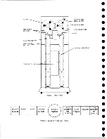
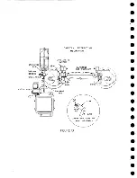
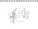
PUSH  ROD

DIAPHRAGM

VACUUM  COLUMN  SWITCHES 

FIGURE  II

Содержание 727

Страница 1: ...IBM T R A D E M A R K 727 magnetic tape unit and tester el e c t ro n ic d ata p r o c e s s i n g mac hi nes customer engineering manual of instruction Form 22 6681 0...

Страница 2: ...Copyright 1956 by International Business Machines Corporation 590 Madison Avenue New York 22 N Y Printed in U S A Form 22 6681 0...

Страница 3: ...ive Clutches 15 11 14 File Protection 40 4 6 Vacuum Columns and Vacuum 11 15 Forward and Reverse Operated Switches 16 Switch 40 4 7 Motor Drive 17 11 16 Machine Ready 75 09 03 40 4 8 Time Delay 17 11...

Страница 4: ...ad In Low Speed Rewind Area 23 2 Manual Control of Tape Motion Page 17 0 PREVENTIVE MAINTENANCE 63 18 0 TYPE 727 RELAY WIRING DIAGRAM 65 19 0 727 TAPE DRIVE TESTER 79 19 1 General 79 19 2 Purpose of S...

Страница 5: ...the systems and write up to be at the same level logically This change should be made on systems page 75 10 01 as follows 1 Remove 12 AU and the lk ohm potentiometer and 500 ohm resistor tied to the...

Страница 6: ......

Страница 7: ...ained externally while power for relay circuitry is self contained The unit is normally connected to EDPM equip ment as an input output device A reel of magnetic tape is an economical storage medium b...

Страница 8: ...turer Each reel is tested twice by IBM before it is shipped to the customer 0 The aim of this intense effort is to eliminate any conditions leading to an error in the recording of information or in th...

Страница 9: ...his means that about 200 bits may be written in one inch of space One 2400 foot reel can contain the information on about 20 000 80 column cards Information may be placed on the tape in any configurat...

Страница 10: ...e resultant flux remains point B Figure 2 Thus by employing suitable circuit techniques a flux pattern of either positive or negative polarity can be impressed on a magnetic material The schematic ske...

Страница 11: ...ic material on the tape as being a series of tiny bar magnets placed end to end Where the change in flux occurs there are like poles where no change occurs there appears to be a long magnet The readin...

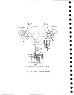
Страница 12: ...es the path of the tape from one reel to the other The next paragraphs describe the mechanics of the tape transportation mechanism The right and left drive capstans turn continuously in the direction...

Страница 13: ...f width of the tape To avoid too complicated an alignment system it was preferred to maintain the alignment of one edge of the tape only and let the other move freely Figure 8 is a view of the split i...

Страница 14: ...the erase head to keep intimate contact between the tape and the read write head As previously stated the erase head is mounted on the upper plate and moves up during high speed rewind time and when t...

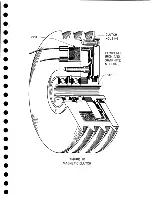
Страница 15: ...coil As soon as current is caused to flow through the coil the rotor begins to move with the housing and to turn the hub and reel at the front of the machine Because of the inductance of the coil curr...

Страница 16: ...vacuum switch in the column the file reel forward left down clutch is energized and the reel turns in a clockwise direction causing more tape to be fed into the left column As soon as the loop is agai...

Страница 17: ...ed rewind an additional motor 1 12 HP 30 208v AC 3450 RPM is provided in the upper left hand corner This motor is coupled to the file reel shaft and during normal tape motion is merely turned with the...

Страница 18: ...enoid allowing the capstans to extend Finally the latch magnet is de energized 4 10 HEAD RAISING MECHANISM The mechanism that raises the upper portion of the head assembly is directly behind the upper...

Страница 19: ...mal writing is prevented 4 13 POWER CONSIDERATIONS All external power is brought into the tape unit through a male Cannon plug lo cated at the lower rear right hand corner of the tape unit Power may b...

Страница 20: ...o the columns and searching for the load point If the tape has been unloaded manually in the fast rewind section of the tape depressing this key executes a high speed rewind before the above operation...

Страница 21: ...is best to do this while the tape is loaded on a unit If this is done away from the unit keep the un rolled end off the floor and away from dusty areas 7 Inspect containers periodically Remove any acc...

Страница 22: ...hip magnetic tape the following procedure is advisable 1 Pack the tape and reel securely in a dust proof container 2 Hermetically seal the container in a plastic bag Ordinary plastic bags that can be...

Страница 23: ...well to the right of the head assembly Close the reel door and press the load rewind button Step 4 The vacuum motor and time delay motor start turning Step 5 At the end of the time delay about five se...

Страница 24: ...transfer R11BU Vacuum column switches have no control over reel clutches 05G Pick R7 cap stans in Capstans in microswitch 10 01 Full power to both stop clutches RIAUn c R4ALn c RIBUn c R4BLn c Power t...

Страница 25: ...w m 04C Pick R2 load rewind R40 ln o w 05C Pick R3 R31 load rewind LT R21 R26 unload R2BLn 0 06H Pick HD4 vacuum mtr R 26 ln c 10 02 Start vacuum mtr HD4 pt 05D Drop R il R22 unload R21 4 04C Hold R2...

Страница 26: ...erse Prepart to extend cap stans Hold until load point is reached The above operations all take place within a fraction of a second after the load rewind button is pressed When sufficient vacuum is ob...

Страница 27: ...tart line goes down 02E pushing the left moving pulley up against its stop capstan pinching the tape The tape then goes into the other col umn dropping RIO If tape were not pinched by dropping R9 the...

Страница 28: ...J Manual reverse line comes up R33 2 Energize the reverse magnet De energize the forward magnet Oil Pick R34 start R33 1 02E Manual start line comes up R34 1 Energize moving coil in the start directio...

Страница 29: ...ions Remarks The moving coil has already been put in a stop status by the line not arriving at load point At the end of the 20ms SST the line goes up again By that time how ever the manual start line...

Страница 30: ...ow from ground through tube 2 the 450 ohm resistor mov ing coil right to left the cathode and plate of tube 9 to 140v A heavy initial current is needed through the moving coil to produce fast action T...

Страница 31: ...arks w 75 09 04A Press unload button R 20 ln c Latch pick R21 un load Door must be closed Reset button dropped R20 The R21 1 points open the circuit to R20 start in a ready status when unloaded so the...

Страница 32: ...and RIO tape out of col umns Col flapper valve m icro switches Tape out of both columns 04A Hold R l R18 rim R11AL 05F Latch pick R26 unload stop RllAU n o h c u p m icro switch R10AU R9AU R5 BL R6BL...

Страница 33: ...arks 02A Push load rewind button and pick R40 rewind PU R42 3n c relay driver 75 08 manual load rewind line and read status Must press reset button first if ready light is on 04C Pick R2 load rewind R...

Страница 34: ...mtr R8AUn c Stop the capstan motor 02E Manual start line up R8BL The unit is now in a for ward start status placing the moving pulleys away from the stop capstans 05G Pick R9 RIO tape out of columns F...

Страница 35: ...clutch 05E Pick DPI take up mtr reverse R6BLn o Prepare to lower head cover 06G 06B Pick HD8 retract caps Pick re tracting solenoid latch R6AUn o R6AL Prepare to extend cap stans 05E HD6 take up mtr T...

Страница 36: ...tion The select line causes the select light to come on through the IL and also conditions the tape indicator control 11 3 READ WRITE STATUS 75 02 Set Read Status Set read status is externally generat...

Страница 37: ...put is used to pick a tape break relay R41 in 75 09 03 This is a latch pick relay that remains latched until an unload condi tion is initiated To stop the reel motion a R41 1 point opens in the circui...

Страница 38: ...control circuitry Therefore current is always flowing through the read write coil in one direction or the other The cir cuit for this is shown on 75 07 and C 01 07 The right and left outputs of a writ...

Страница 39: ...nd of a block of information indicates whether an odd or even number of l fs has been written If an odd number of l fs has been written the write trigger is on If an even number of l fs has been writt...

Страница 40: ...f tape The tool consists of two push buttons that may be connected through a cord and Jones plug to the machine The connection is shown on 75 09 01 If the forward button is pressed R34 is energized wh...

Страница 41: ...ed and is ready to begin reading The term ready here means that a tape is loaded into the machine and the machine is not in rewind status This is in reality a response to the set read line coming from...

Страница 42: ...rite triggers Backward 75 05 01 This line also originates at the control system and con trols the status of the forward reverse magnet in the selected unit Start Rewind 75 08 This is a line originatin...

Страница 43: ...or the rate of change of the discontinuity Similarly noise errors arise from discontinuties in the magnetic coating on the tape surface Surface irregularities also contribute to noise Other sources of...

Страница 44: ...mplifier Tracking in a strict sense is the lateral agreement of the individual tracks of the read write head with the signal tracks on tape This depends on the lateral position of the tape with respec...

Страница 45: ...Therefore if the effective air gap widths of two tracks are different they will exhibit skew on their own tape Air gap width differences are caused by difference in skim material thickness and fit of...

Страница 46: ...d up being off If not keep writing short records until they do end up being o ff 2 Press the reset button on the tape drive 3 Unload and develop the tape 4 If the polarity of the erase head is correct...

Страница 47: ...4 T02J 5 14 4 CHECKING FOR REVERSAL FAILURES Trouble encountered while running programs involving backspacing even though the tape drive is in correct adjustment may be due to reversal failures A che...

Страница 48: ...king the head sections 15 2 ADJUSTMENT OF HEAD ASSEMBLY FIGURE 18 15 2 1 Limit Stops Adjustment Make this adjustment as follows 1 Remove power and operate jackshaft manually 2 Loosen mounting screws o...

Страница 49: ...e surface plate to determine the position The entire head assembly P N 333072 should be returned to the factory if any trouble is encountered with the read write heads or split idlers 15 2 6 Skew Adju...

Страница 50: ...o peak across one coil of the head on one or more tracks when tape written with that head is read The head should also be replaced when there is a signal of less than 30mv peak to peak across one coil...

Страница 51: ...inges on upper main plate and be sure they are tight 9 Remove upper head cover 10 Remove 6 Allen head screws and plated washers from the upper main plate 11 Carefully lower the upper main plate until...

Страница 52: ...l and Adjustment of the Vacuum Columns Figure 22 Two methods are used to fasten the vacuum columns to the lower main plate On earlier machines two mounting screws are used per column on current machin...

Страница 53: ...ferred to their rear positions Change the above adjustment if necessary 15 6 3 Adjustment of Flapper Valve Switches Adjust right and left flapper valve switches so that they are depressed and make wit...

Страница 54: ...stan retracting slide assembly The needle bearings are held in a race so that there is no danger of their falling out 15 7 2 Removal of a Capstan Housing Remove the capstan drive belt On the retractin...

Страница 55: ...ed The capstans in microswitch operating cam 5 should be adjusted to operate the switch slightly before capstans reach a fully retracted position The capstans in microswitch must remain operated after...

Страница 56: ...le in both a forward and reverse status The start stop times in either direction should be as nearly equal as the tolerances of the system will allow The adjustments must be made in the following orde...

Страница 57: ...magnet arma ture and move the moving coil up Adj st the lock nuts at 2 3 on the reverse mag net side to obtain 020 001 clearance from the forward or right moving pulley to the drive capstan 4 Do this...

Страница 58: ...ould not strike its drive capstan as the pulley moves from a stop position to a neutral position 2 Check in the forward condition by moving the motion control switch from stop to forward several times...

Страница 59: ...This status is the same as above except that the positive trigger input is from 01J P1 and the input signal is obtained with probe on 01J P6 See section 19 4 4 15 8 8 Moving Coil Wave Form The tape un...

Страница 60: ...s above the DC change in level of the photo cell output from tape under the photo cell to reflective spot under the photo cell must not be less than 10 volts Measure between ground and the white lead...

Страница 61: ...ritten on one machine and read on a different ma chine 15 9 10 Reel Hub Shimming Adjustment When the reel hub knob is turned in a clockwise direction from the front of the machine the steel cover over...

Страница 62: ...oints in tape drive linkage Inspect oilite bearings in capstans housings and moving pulley periodically for wear or gum accumulation Replace or clean as necessary Split idlers and rewind idlers moving...

Страница 63: ...tage 60 Recommended Test Limits 54 78 130 117 137 140 133 150 NOTE In case of random tape errors that are not revealed in above tests try varying voltages in the central processing unit while operatin...

Страница 64: ...ncluding total rewind time starting at critical point creeping of machine reel and tape break circuitry 11c Clean the column head capstans idlers and so on lid Check the vacuum columns including the b...

Страница 65: ...a partial duplication of the tape drive unit systems dia gram It should be used as an aid in learning not in servicing the machine For simplicity the wiring is not shown point to point A convenient f...

Страница 66: ...9 G F A F E 10 G F A F E 11 D F A H G 12 F E 13 H 14 H A C FP B J AC DC Fuse Micro switch A Capstans in micro switch G Capstans out micro switch D Door interlock A F P sensing pin B Fwd Rev manual pus...

Страница 67: ...co Q...

Страница 68: ......

Страница 69: ...To Fuse 13 48V...

Страница 70: ......

Страница 71: ......

Страница 72: ......

Страница 73: ...o IC To Fuse 13 48V...

Страница 74: ......

Страница 75: ......

Страница 76: ......

Страница 77: ...Rew Intik 75 08 o T l C o n ro Rewind P U Tape Break Load Point c LP R41 pLP R42 v t r p c I R19 Rev Sol Fwd Sol R40 I Reverse 75 05 02 Rewind 75 08 Tape Break 75 03 L P Pick 75 04 Drop L P Relay 75...

Страница 78: ......

Страница 79: ...e 2 power connector pin 2 becomes positive maximum before Phase 3 power connector pin 3 becomes positive maximum When turning on the AC wait 30 seconds to allow filaments to heat before turn ing on th...

Страница 80: ...ressing this button turns on the go backward trigger TR normally bringing up the go line If the go fb switch is set to forward backward7 however the output of this trigger brings up the backward line...

Страница 81: ...o put it under external control Select the tape drive by setting the address selector switch of both the drive and the TDT to the same address Unless otherwise noted the start stop switch is off the m...

Страница 82: ...nsed The ma chine then rewinds the tape back to the load point Upon reaching the load point the tape unit starts writing again and the cycle is repeated This operation is accomplished in the following...

Страница 83: ...the start stop envelope produced by the tape drive unit set the oscilloscope as follows external sync to go fb hub input to read bus hub vertical calibration at ten volts per major division and horiz...

Страница 84: ...section 15 2 6 19 4 4 Checking Forward Reverse Magnet Transfer The tape unit is loaded selected and read The tester switches are set as fol lows read write switch on READ manual switch in neutral the...

Страница 85: ...f the reel arm switch is closed or when the reset key is pressed while rewinding in the high speed area It is the hold point for R2 When initiating a rewind in the slow speed area it prevents a short...

Страница 86: ...rewind or unload operation Energize HD8 in preparation to letting capstans out during the load rewind from an unloaded status or during loading portion of a high speed rewind Energize the solenoid ma...

Страница 87: ...drop the run relays if tape should break during any opera tion where tape is being moved by the drive capstans These prevent braking the left reel while slowing down from a high speed rewind These ho...

Страница 88: ...01 It is always picked when 48v power is on machine When dropped it indicates a burned out photo light 14AL 09 04 Drop the run relays if any photo light burns out while low speed rewinding or if the...

Страница 89: ...is up and tape is out of both columns Drop R26 when a load rewind operation starts Stop the vacuum motor HD4 Stop the take up motor HD6 when unload is completed Prevent continuous energization of R26L...

Страница 90: ...R7BU to control the rewind interlock line It is added protection to insure that the read write status trigger is held off while rewinding Prevent the ready light from being on while rewinding It is pi...

Страница 91: ...rive tester Mechanical adjustments False load point and tape break indicator Cleaning procedure Humidity conditions Tape break circuitry Shortage of 6072 tubes Test for erase and read write head polar...

Страница 92: ......

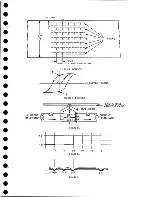
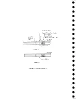
Страница 93: ...039 0035 FIGURE 1 BIT PO SITIO N S O N TAPE CURRENT GENERATOR FIGURE 3c...

Страница 94: ...G ARM MACHINE REEL UPPER M AIN PLATE TAPE VACUUM SWITCHES 4 FIGURE 4 FRO N T VIEW SELECT LIGHT RESET START READY LIGHT FILE PROTECT ON LIGHT LOAD REWIND UNLOAD TAPE INDICATE ON LIGHT FIGURE 5 PANEL BU...

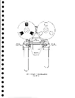
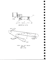
Страница 95: ...w PATH OF TAPE THROUGH MACHINE FIGURE 6...

Страница 96: ...RIG HT STOP CAPSTAN LEFT STOP CAPSTAN M O VING PULLEY M O VING PULLEY MECHANISM SHOWN IN A FORWARD STOP STATUS FIGURE 7 MOVING COIL AND LIN KA G E REAR VIEW...

Страница 97: ...SPLIT IDLER ASSEMBLY FIGURE 8...

Страница 98: ......

Страница 99: ...CLUTCH HOUSING POWDERED IRON AND GRAPHITE MIXTURE FIGURE 10 MAGNETIC CLUTCH...

Страница 100: ...PUSH ROD DIAPHRAGM VACUUM COLUMN SWITCHES FIGURE II...

Страница 101: ...BACKWARD MOTOR CAPSTAN MOTOR FORWARD MOTOR...

Страница 102: ...LATCH FIGURE f3...

Страница 103: ...140 140...

Страница 104: ...ATUS START REWIND _ TAPE DRIVE UNIT S s S SEL a TAPE IND OFF TURN OFF TAPE IND SEL a TAPE IND ON TURN ON TAPE IND SET WRITE STATUS SEL READY a WRITE s SET READ STATUS SELECT READY a READ WRITE BUS 7 _...

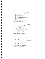
Страница 105: ...IGURE 16a TOP VIEW OF READING HEAD SHOWING HEAD SKEW MECHANICAL FIGURE 16b TOP VIEW OF READING HEAD SHO W ING POOR HEAD A LIG N M EN T Back Plate Tape FIG URE 16c TOP VIEW OF READING HEAD SHO W ING PO...

Страница 106: ...R W Status Tg r Turning O ff Write Heads Information Already on Tape 1 Stopping Distance Record Written All Tape Motion Correct Polari y Bits FIGURE 17a Tape Motion Incorrect Polarity FIGURE 17b FIGU...

Страница 107: ...FIGURE 18 HEAD ASSEMBLY A DJUSTM ENTS...

Страница 108: ...TAPE C LEA N ER FIG URE 19...

Страница 109: ...VACUUM COLUMN ADJUSTMENT FIG U RE 22...

Страница 110: ...DRIVE MOTOR PULLEY CAPSTAN DRIVE BELT TENSION FIGURE 23 REAR VIEW S...

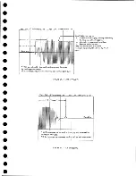
Страница 111: ...ive tape at both capstans b Worn pin in capstan drive pulley c Pressure pad adjustment Keep this reduction at a minimum The signal level should be stable by 7 1 2 msec FIGURE 24 START ENVELOPE Vert Ca...

Страница 112: ...Cal 20 Volts M ajor Div H o r C a l 4 Msec Major Div FIGURE 26 REVERSE MAGNET TRANSFER VER C A Lr 5 0 M AMPS MAJOR DIV HOR CAL r 5 MSEC MAJOR DIV THIS IS 0 5 VOLTS MAJOR DIV FIGURE 27 MOVING COIL WAV...

Страница 113: ...CONTROL UNIT TAPE DRIVE TESTER FIGURE 28 TAPE DRIVE TESTER CO NN EC TIO N S...

Страница 114: ...P FREQUENCY IwewimlI O I B IT SW IT C H ES l I C B A 8 4 2 T 1 c j c j cj Q Q FIGURE 29 727 TAPE DRIVE TESTER GO Reset Write Tgrs Write Pulses A B T O i i i i I l i t i l i 100 usee n n T 100 I I I I...

Страница 115: ...NS R35 36 01 D REWIND STATUS HR6BU LOAD REWIND PRESSED COL M S N OV A C SW RIAL RIBL R9 I0BL R9 I0 05G TAPE OUTCOLS RIJ8 04A RUN HDL2 06H PHASE L2 R4104D CLUTCH IP R4 RIGHT LEFT M COIL STA H C DOWN M...

Страница 116: ...FIGURE 32 HIGH SPEED REWIND...

Страница 117: ...omatically at any time the motor is running Sensing switches on each drive sense whether the capstans are in or out The sensing switches are magnetically operated Figure 34 When the motor is not runni...

Страница 118: ...s AND circuit E32F which AND ed T trewind inter lock statusff with photo cell output to relay driver T05J7B to pick tape break relay Reason for this omission is that the tape break relay has been omit...

Страница 119: ...later in the sequence Relay 8 completes the circuit to the timer motor and the timer starts Next in the sequence the vacuum motor pumps enough air to operate the column flapper switches The flappers...

Страница 120: ...4n o points open to bring down At L P to AND circuit G20F 76 04 This results in a down level to the relay driver T04J5B allowing R26 to fall With the C E switch set to stop R27 is allowed to fall Thi...

Страница 121: ...arting with tape setting at load point depressing the unload button results in the following sequence Figure 38 The unload button latch picks R15 and R15 2 n o closes to pick RIO Relays 2 and 28 are p...

Страница 122: ...zation of the capstan drive motors N C points pick DP2 so that the capstan motors are running only when R2 is down N O points energize the head lock solenoid so that the head will be unlocked and free...

Страница 123: ...the tape break load point TI lamps when 48 volts is up Drops as a result of a failure of any of the lamp filaments Drops R l HD1 2 and 3 with a photo light failure Interlocks picking R21 rewind PU wh...

Страница 124: ...C E switch when the tape drive is in use with the CPU or other I O machines Hold point for R13 Drops relay reset to 76 02 so that the R W triggers can be operated Opens the circuit to the load rewind...

Страница 125: ...6 09 02 Makes a circuit to pick R24 and R27 during high speed re wind R24 High speed re Picks at any time that R23 picks wind interlock 76 09 02 24 1 76 09 09 Opens and allows the tape break light to...

Страница 126: ...E switch 76 09 02 Manually operated single pole three position switch When the switch is set to forward go R27 is picked When it is set to backward go R27 and the manual reverse line comes up Left and...

Страница 127: ...Start push button 76 09 08 Head up switch 76 09 09 Picks R13 when depressed The points shown are the normally open points of a m icro switch They are closed when the head is up 127...

Страница 128: ...orward to drive position and aligning the permanent mag net position B with steel disc A The switch assembly should be set so that the magnet is attracted to the steel disc with a minimum of 010 inch...

Страница 129: ...A Capstan Out 13 16 iS i Aftr _ V 1 im m 1 W F B Capstan Retracted FIGURE 33 CAPSTAN DRIVE M O TO R 727 MODEL III...

Страница 130: ...Right Capstan Motor Bottom View Sensing Switch Assy Capstan Out FIGURE 34 CAPSTAN SEN SIN G SW ITCHES 727 MODEL III...

Страница 131: ...u r 4 ll_ _ J Take Up AAotor A v Mead p o Down Micro Sw X Y K Z p O Q lurch status i X L K Zo v lutch Status z Y a L U rZ p 17 Capstan Motors b K 1 Power on Reset c j Capstan in ow l cx k a Capst D 07...

Страница 132: ...art N R 25 Load Point P R 26 Load Point Trip Q 48 Volts to Man Rev N T U L L R R 21 Rwnd P U S R 3 Load Rwnd 1 R T R 9 Load Rwnd 2 U R l2 Rwnd Status C E Switch set to Fwrd Tape Drives Forward n C E S...

Страница 133: ...Z DPI Take Up Motor Rev a R 4 Arm Switch b R 8 Delay Timer Motor c Time Delay Points d 48 Volts to Man Rev e 48 Volts to Man St f R 25LP Load Point g Arm Switch W V wmm mmmmmm F W B B Depress Load Rw...

Страница 134: ...l o i L P N P R 5 L T Load Point psb t L 11 m ia u e K V R u p loK up M otor st Head Down M ic ro Sw itch S Head Up MIere Switch T Column Switches U R 5 R 6 V R l LP Unload Stop W T l L P Lights X HD4...

Страница 135: ......

Страница 136: ...v n...

Страница 137: ......

Страница 138: ......

Страница 139: ......

Страница 140: ......

Страница 141: ......

Страница 142: ......

Страница 143: ......

Страница 144: ......

Страница 145: ......

Страница 146: ......

Страница 147: ......

Страница 148: ......

Страница 149: ......

Страница 150: ......

Страница 151: ......

Страница 152: ......

Страница 153: ......

Страница 154: ......

Страница 155: ......

Страница 156: ......

Страница 157: ......

Страница 158: ......

Страница 159: ......

Страница 160: ......

Страница 161: ......

Страница 162: ......

Страница 163: ......

Отзывы: