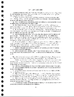
8. If a tape break occu rs, divide the reel into two sm aller reels. Splicing is
not recommended. If it is necessary to make a temporary splice in order to recover
information, be sure to use special low cold flow splicing tape.
9. Dropping a reel can easily damage both the reel and the tape. General use of
a reel and tape after it has been dropped is usually unsatisfactory.
10. Never throw or mishandle reels, even while they are protected in their
containers.
Magnetic tape is sensitive to changes in humidity and temperature. Note the
following recommendations.
1. If at all possible, store the tape where it is to be used, e. g . , in the calcula
tor room . Location of tape storage near the tape drives reduces both handling and
variations in atmospheric conditions.
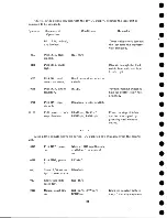
2. The atmosphere should be controlled between the following limits:
(a) relative humidity
40-60%
(b) temperature
65°-80°F
3. If the tape must be removed from the calculator atmosphere, hermetically
seal it in a plastic bag. If the tape is not hermetically sealed then, before re-u se it
must be returned and allowed to remain in the calculator atmosphere for a length of
time equal to the time it was away from the room . Twenty-four-hour conditioning is
necessary if the tape has been removed for a time greater than 24 hours.
When custom ers ship magnetic tape, the following procedure is advisable.
1. Pack the tape and reel securely in a dust proof container.
2. Hermetically seal the container in a plastic bag. (Ordinary plastic bags that
can be sealed with a hot iron should be available from local m erchants.)
3. Obtain additional support by enclosure in individual stiff cardboard shipping
boxes.
For long-term storage, take the following precautions.
1. Provide proper mechanical support for the reels by using the dust proof con
tainers.
2. Enclose the reel and container in a herm etically-sealed m oisture-proof plastic
bag.
3. Store in an area of constant temperature. Either freezing or excessive tem
peratures could harm the tape. A temperature between 40° and 120°F is satisfactory.
The following are points of general tape-handling information.
1. The procedures outlined above apply to handling tape in a 701 installation as
well as 702 and 705 installations.
2. Customer engineers and other IBM personnel should take special precautions
to follow the tape handling recommendations to show, by example, the care required
to insure good tape perform ance.
3. Replace any tape arriving at the cu sto m e rs installation in unusable condition
and return the faulty tape to the factory. To aid the factory in its inspection, ship the
tape according to the shipping instructions outlined above.
4. Use discretion about smoking in the vicinity of tape because it adds to the dirt
problem . A hot ash could cause serious trouble with a reel of tape.
22
Содержание 727
Страница 6: ......
Страница 67: ...co Q...
Страница 68: ......
Страница 69: ...To Fuse 13 48V...
Страница 70: ......
Страница 71: ......
Страница 72: ......
Страница 73: ...o IC To Fuse 13 48V...
Страница 74: ......
Страница 75: ......
Страница 76: ......
Страница 78: ......
Страница 92: ......
Страница 93: ...039 0035 FIGURE 1 BIT PO SITIO N S O N TAPE CURRENT GENERATOR FIGURE 3c...
Страница 95: ...w PATH OF TAPE THROUGH MACHINE FIGURE 6...
Страница 97: ...SPLIT IDLER ASSEMBLY FIGURE 8...
Страница 98: ......
Страница 99: ...CLUTCH HOUSING POWDERED IRON AND GRAPHITE MIXTURE FIGURE 10 MAGNETIC CLUTCH...
Страница 100: ...PUSH ROD DIAPHRAGM VACUUM COLUMN SWITCHES FIGURE II...
Страница 101: ...BACKWARD MOTOR CAPSTAN MOTOR FORWARD MOTOR...
Страница 102: ...LATCH FIGURE f3...
Страница 103: ...140 140...
Страница 107: ...FIGURE 18 HEAD ASSEMBLY A DJUSTM ENTS...
Страница 108: ...TAPE C LEA N ER FIG URE 19...
Страница 109: ...VACUUM COLUMN ADJUSTMENT FIG U RE 22...
Страница 110: ...DRIVE MOTOR PULLEY CAPSTAN DRIVE BELT TENSION FIGURE 23 REAR VIEW S...
Страница 113: ...CONTROL UNIT TAPE DRIVE TESTER FIGURE 28 TAPE DRIVE TESTER CO NN EC TIO N S...
Страница 116: ...FIGURE 32 HIGH SPEED REWIND...
Страница 129: ...A Capstan Out 13 16 iS i Aftr _ V 1 im m 1 W F B Capstan Retracted FIGURE 33 CAPSTAN DRIVE M O TO R 727 MODEL III...
Страница 130: ...Right Capstan Motor Bottom View Sensing Switch Assy Capstan Out FIGURE 34 CAPSTAN SEN SIN G SW ITCHES 727 MODEL III...
Страница 135: ......
Страница 136: ...v n...
Страница 137: ......
Страница 138: ......
Страница 139: ......
Страница 140: ......
Страница 141: ......
Страница 142: ......
Страница 143: ......
Страница 144: ......
Страница 145: ......
Страница 146: ......
Страница 147: ......
Страница 148: ......
Страница 149: ......
Страница 150: ......
Страница 151: ......
Страница 152: ......
Страница 153: ......
Страница 154: ......
Страница 155: ......
Страница 156: ......
Страница 157: ......
Страница 158: ......
Страница 159: ......
Страница 160: ......
Страница 161: ......
Страница 162: ......
Страница 163: ......


