72 7 M O D E L III T A P E D R I V E
22.0 INTRODUCTION
22.1
MECHANICAL PRINCIPLES
The differences between the Model I 727 and the Model II 727 are minor, consist
ing only of cover changes. The Model III changes are described in this appendix; the
mechanical changes are described in this section.
The magnetic-clutch mounting assembly on Models I and II tape drive is built of
fabricated steel plate. On the Model III, the clutches are mounted on a single casting.
Preloaded bearings are now used in the magnetic clutches to eliminate axial travel (end
play) between the clutch rotor and housing,,
The capstan drive motor, belt, and retracting mechanism have been replaced by
two individual capstan drive m otors. These m otors are 1/20 HP, 60 cycle, 3 phase,
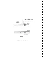
208 volt, reluctance synchronous motors (Figure 33).
The capstans and rotor are attached directly to the motor shaft. The shaft is fitted
to have 13/16-inch axial travel within the motor housing. The complete assembly is
spring loaded to hold the capstan in a retracted position when no power is applied to the
motor. When power is applied to the motor, the rotor is pulled forward; it aligns itself
between the field co ils. This causes the drive capstans to com e out into drive position
automatically at any time the motor is running. Sensing switches on each drive sense
whether the capstans are in or out.
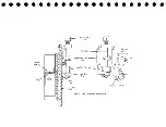
The sensing switches are magnetically operated (Figure 34). When the motor is
not running, the rotor shaft is forced into a retracted position by the capstan retracting
spring.
The steel disc mounted on the read end of the motor shaft is then close to the
permanent magnet that is mounted on the capstan-in switch operating arm. The magnet
is attracted to the steel disc causing the m icroswitch to be operated. When power is
applied to the m otor, the steel disc is moved forward with the motor shaft, allowing
the capstan-in switch to return to normal. The capstan-out switch operates when the
disc has moved near to the permanent magnet attached to its operating lever.
The fabricated steel vacuum columns on Models I and II are replaced by extruded
aluminum columns on the Model III. The plastic front plates on the vacuum columns
are replaced with glass plates. These glass plates present a harder wearing surface
to the tape and prevent the tape from cutting the plates near the areas where the limit
switches are located.
M ercury switches are now used on the manifold flapper valves for sensing instead
of m icrosw itches. They eliminate marginal adjustment conditions that were present
when the previous type switch was used.
OnO'Other mechanical change is that one blower has been omitted from the tube
gate.
117
Содержание 727
Страница 6: ......
Страница 67: ...co Q...
Страница 68: ......
Страница 69: ...To Fuse 13 48V...
Страница 70: ......
Страница 71: ......
Страница 72: ......
Страница 73: ...o IC To Fuse 13 48V...
Страница 74: ......
Страница 75: ......
Страница 76: ......
Страница 78: ......
Страница 92: ......
Страница 93: ...039 0035 FIGURE 1 BIT PO SITIO N S O N TAPE CURRENT GENERATOR FIGURE 3c...
Страница 95: ...w PATH OF TAPE THROUGH MACHINE FIGURE 6...
Страница 97: ...SPLIT IDLER ASSEMBLY FIGURE 8...
Страница 98: ......
Страница 99: ...CLUTCH HOUSING POWDERED IRON AND GRAPHITE MIXTURE FIGURE 10 MAGNETIC CLUTCH...
Страница 100: ...PUSH ROD DIAPHRAGM VACUUM COLUMN SWITCHES FIGURE II...
Страница 101: ...BACKWARD MOTOR CAPSTAN MOTOR FORWARD MOTOR...
Страница 102: ...LATCH FIGURE f3...
Страница 103: ...140 140...
Страница 107: ...FIGURE 18 HEAD ASSEMBLY A DJUSTM ENTS...
Страница 108: ...TAPE C LEA N ER FIG URE 19...
Страница 109: ...VACUUM COLUMN ADJUSTMENT FIG U RE 22...
Страница 110: ...DRIVE MOTOR PULLEY CAPSTAN DRIVE BELT TENSION FIGURE 23 REAR VIEW S...
Страница 113: ...CONTROL UNIT TAPE DRIVE TESTER FIGURE 28 TAPE DRIVE TESTER CO NN EC TIO N S...
Страница 116: ...FIGURE 32 HIGH SPEED REWIND...
Страница 129: ...A Capstan Out 13 16 iS i Aftr _ V 1 im m 1 W F B Capstan Retracted FIGURE 33 CAPSTAN DRIVE M O TO R 727 MODEL III...
Страница 130: ...Right Capstan Motor Bottom View Sensing Switch Assy Capstan Out FIGURE 34 CAPSTAN SEN SIN G SW ITCHES 727 MODEL III...
Страница 135: ......
Страница 136: ...v n...
Страница 137: ......
Страница 138: ......
Страница 139: ......
Страница 140: ......
Страница 141: ......
Страница 142: ......
Страница 143: ......
Страница 144: ......
Страница 145: ......
Страница 146: ......
Страница 147: ......
Страница 148: ......
Страница 149: ......
Страница 150: ......
Страница 151: ......
Страница 152: ......
Страница 153: ......
Страница 154: ......
Страница 155: ......
Страница 156: ......
Страница 157: ......
Страница 158: ......
Страница 159: ......
Страница 160: ......
Страница 161: ......
Страница 162: ......
Страница 163: ......


