


Completing the installation
To complete the installation of the UPS, complete the following steps:
1. If you are installing the IBM UPS Manager software, see “Installing the UPS
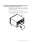
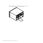
2. If you have not already done so, connect a computer to the UPS by using one
of the communication cables that comes with the UPS.
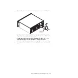
3. If the rack cabinet has conductors for grounding or bonding of ungrounded
metal parts, connect the ground cable (purchased separately) to the ground
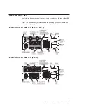
bonding screw. For the location of the ground bonding screw for each UPS
model, see “Rear view of the UPS” on page 7.
4. If an emergency power-off (disconnect) switch is required by local codes, see
“Installing the remote emergency power-off” to install the remote emergency
power-off switch before you turn on the UPS.
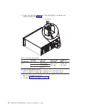
5. Connect the devices that you want to protect to the applicable UPS output
receptacles. Do not turn on the devices. For information about load segments,
see “Configuring load segments” on page 27.
Notes:
1.
Do not
protect laser printers with the UPS because of the exceptionally high
power requirements of the heating elements.
2. Before you connect the UPS power cord to a power source, see “UPS initial
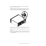
Installing the remote emergency power-off
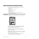
The UPS includes a remote emergency power-off connector that enables you to
turn off power at the UPS output receptacles from a customer-supplied switch in a
remote location. For example, you can use this feature to shut down the load and
the UPS by thermal relay, in the event of a room overtemperature condition. When
a remote emergency power-off is activated, the UPS shuts down the output and all
its power converters immediately. The UPS logic power remains on to issue an
alarm.
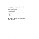
The remote emergency power-off feature shuts down the connected devices
immediately and does not follow the orderly shutdown procedure that is initiated by
any power-management software.
Any devices that are operating on battery power are also shut down immediately.
When the remote emergency power-off switch is reset, the connected devices will
not return to battery power until the UPS is restarted manually.
Notes:
1. The remote emergency power-off contacts are open by default. To change this
setting, see the REPO setting in Table 8 on page 24.
2. For Europe, the emergency switch requirements are detailed in Harmonized
document HD-384-48 S1, “Electrical Installation of the Buildings, Part 4:
Protection for Safety, Chapter 46: Isolation and Switching.” For more
information, see the European Committee for Electrotechnical Standardization
website at http://www.cenelec.eu/.
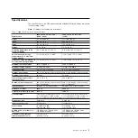
Table 3. Remote emergency power-off connections
Wire function
Terminal wire size rating
Suggested wire size
Remote emergency power-off 4-0.32 mm
2
(12-22 AWG)
0.82 mm
2
(18 AWG)
Chapter 2. Installing the uninterruptible power supply
11
Содержание 6000 VA LCD 4U
Страница 1: ...6000 VA LCD 4U Rack UPS 6000 VA UPS 3U Extended Battery Module Installation and Maintenance Guide...
Страница 2: ......
Страница 3: ...6000 VA LCD 4U Rack UPS 6000 VA UPS 3U Extended Battery Module Installation and Maintenance Guide...
Страница 14: ...xii 6000 VA UPS and 6000 VA EBM Installation and Maintenance Guide...
Страница 32: ...18 6000 VA UPS and 6000 VA EBM Installation and Maintenance Guide...
Страница 60: ...46 6000 VA UPS and 6000 VA EBM Installation and Maintenance Guide...
Страница 70: ...56 6000 VA UPS and 6000 VA EBM Installation and Maintenance Guide...
Страница 74: ...60 6000 VA UPS and 6000 VA EBM Installation and Maintenance Guide...
Страница 82: ...68 6000 VA UPS and 6000 VA EBM Installation and Maintenance Guide...
Страница 86: ...72 6000 VA UPS and 6000 VA EBM Installation and Maintenance Guide...
Страница 87: ......
Страница 88: ...Part Number 81Y1032 Printed in USA 1P P N 81Y1032...


