


Low battery alarm or error message
Symptom:
The UPS does not power on or there is an immediate or near
immediate low battery alarm or error message.
Solution:
If you are installing a new UPS, check the battery date sticker on the
body of the battery. If the date is less than one year, replace the battery. If it is older
than one year and it is a new installation, do one of the following actions:
v
If the UPS came directly from IBM, replace the batteries.
v
If the UPS came from an IBM Business Partner, contact the IBM Business
Partner for battery replacement.
For the latest UPS FRU and CRU parts, see http://www.ibm.com/support/
docview.wss?uid=psg1MIGR-64944.
For more information about replacing the batteries, see Retain tip H193929 at
http://www.ibm.com/support/entry/portal/docdisplay?lndocid=migr-5077486.
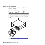
Recharging internal batteries
The UPS internal batteries are charged to approximately 80 percent before they are
shipped. The UPS is shipped with the internal battery connector disconnected, to
avoid premature discharge of the battery. The battery is expected to last at least six
months from the manufacture date, before requiring a recharge of the battery. If the
UPS is kept in storage after the first recharge, repeat subsequent recharges every
six months. Batteries must be connected before each recharge and disconnected
after each recharge. However, do not recharged the batteries more than twice
because it might limit the overall battery storage period to 18 months or less.
The recharge period for a battery is 24 hours without any load attached to the UPS
and if the following conditions are met:
v
Storage temperature: +10 - 40°C (+50 - 104°F)
v
Storage relative humidity: 0 - 95%
v
Storage elevation: 0 - 15,000 m (0 - 49,212 ft)
If the storage length of time goes beyond the recharge date, the battery of the UPS
unit might drain completely. In this case, the batteries cannot be recharged and are
considered to be damaged and must be replaced.
For more information about recharging the internal batteries, see Retain tip
H193929 at http://www.ibm.com/support/entry/portal/docdisplay?lndocid=migr-
5077486.
Chapter 6. Troubleshooting
55
Содержание 6000 VA LCD 4U
Страница 1: ...6000 VA LCD 4U Rack UPS 6000 VA UPS 3U Extended Battery Module Installation and Maintenance Guide...
Страница 2: ......
Страница 3: ...6000 VA LCD 4U Rack UPS 6000 VA UPS 3U Extended Battery Module Installation and Maintenance Guide...
Страница 14: ...xii 6000 VA UPS and 6000 VA EBM Installation and Maintenance Guide...
Страница 32: ...18 6000 VA UPS and 6000 VA EBM Installation and Maintenance Guide...
Страница 60: ...46 6000 VA UPS and 6000 VA EBM Installation and Maintenance Guide...
Страница 70: ...56 6000 VA UPS and 6000 VA EBM Installation and Maintenance Guide...
Страница 74: ...60 6000 VA UPS and 6000 VA EBM Installation and Maintenance Guide...
Страница 82: ...68 6000 VA UPS and 6000 VA EBM Installation and Maintenance Guide...
Страница 86: ...72 6000 VA UPS and 6000 VA EBM Installation and Maintenance Guide...
Страница 87: ......
Страница 88: ...Part Number 81Y1032 Printed in USA 1P P N 81Y1032...


