


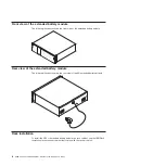
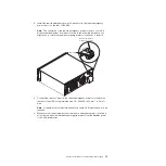
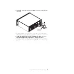

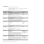
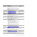
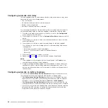
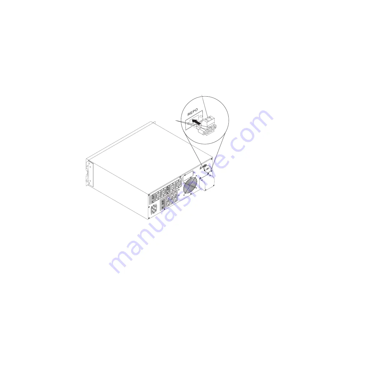
3. Install the remote emergency power-off connector in the remote emergency
power-off port on the rear of the UPS.
Note:
The orientation of the remote emergency power-off port on your UPS
model might be different from what is shown in the following illustration. You
might have to rotate the remote emergency power-off connector to install it.
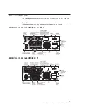
Remote emergency
power-off connector
Openings
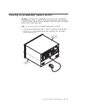
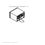
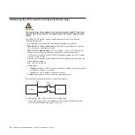
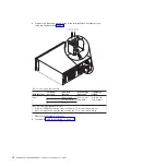
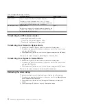
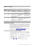
4. Connect the switch or circuit to the remote emergency power-off connector on
the rear of the UPS, using insulated size 18 - 20 AWG (0.75 mm
2
- 0.5 mm
2
)
wire.
Note:
A separate contact must simultaneously cause UPS input ac power to be
removed.
5. Make sure that the externally connected remote emergency power-off switch is
not activated. An activated remote emergency power-off switch disables power
to the UPS receptacles.
Chapter 2. Installing the uninterruptible power supply
13
Содержание 6000 VA LCD 4U
Страница 1: ...6000 VA LCD 4U Rack UPS 6000 VA UPS 3U Extended Battery Module Installation and Maintenance Guide...
Страница 2: ......
Страница 3: ...6000 VA LCD 4U Rack UPS 6000 VA UPS 3U Extended Battery Module Installation and Maintenance Guide...
Страница 14: ...xii 6000 VA UPS and 6000 VA EBM Installation and Maintenance Guide...
Страница 32: ...18 6000 VA UPS and 6000 VA EBM Installation and Maintenance Guide...
Страница 60: ...46 6000 VA UPS and 6000 VA EBM Installation and Maintenance Guide...
Страница 70: ...56 6000 VA UPS and 6000 VA EBM Installation and Maintenance Guide...
Страница 74: ...60 6000 VA UPS and 6000 VA EBM Installation and Maintenance Guide...
Страница 82: ...68 6000 VA UPS and 6000 VA EBM Installation and Maintenance Guide...
Страница 86: ...72 6000 VA UPS and 6000 VA EBM Installation and Maintenance Guide...
Страница 87: ......
Страница 88: ...Part Number 81Y1032 Printed in USA 1P P N 81Y1032...


