11
Rev.
141203
i3-TRNG-CAMS-
Ax73RM
.indd
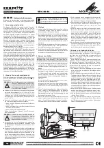
4.1 Flush Mounting w/ locking arms (indoor)
Locking
arms (x2)
1. Use the Flush Mounting Template to cut a hole into the mounting surface.
Insert the camera inside the surface opening.
2. Turn two black-coloured screws on the camera module clockwise to engage the
locking arms. Tighten the arms securely against the mounting surface.
3. Adjust the lens angle by rotating and panning the camera lens base. Do not
over-rotate the camera lens beyond the stop point to avoid damage to the
camera. Keep the camera tilt angle at >17°.
See section 4.6 for more info.
Tip:
For the ease of setup, lift off the camera liner while adjusting the lens
position.
4. Once the desired view has been achieved, replace the camera liner until it snaps
back into place.
5. Replace the camera dome housing on top of the camera module. Use the red
dots on both modules for easy alignment.
6. Use the supplied Torx bit to re-tighten 3 silver screws securing the dome bubble
housing to the camera module.
Note on supplied mounting hardware:
Based on installation location and surface type, supplied screws and
anchors may not be adequate. Mounting hardware is site-specific
and may need to be supplied by the installer.
This
indoor
installation method is suitable for drywall and T-bar installations only.
Do not use this mounting method for outdoor installations.
Do not use camera’s back box for this installation method.
Note: It is the installer’s responsibility to ensure that the mounting surface is suitable
for installation method.


