Working principle of FAM
FAM 5
en(us)
31 / 100
BEWA FAM5 3667663b en-us 2012-12-12.doc
2012-12-12
Working principle of FAM
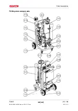
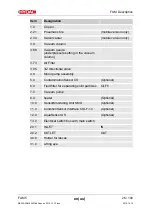
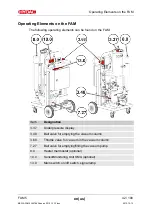
After you switch on the FAM, the motor pump assembly (4.0), depending on
the fill level in the vacuum column, starts to suck either from the vacuum
column or the tank via the suction strainer (4.02) or from the vacuum column
and the 3/2 directional valve (3.85).
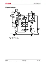
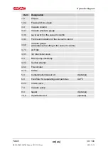
The flow rate is split up in the flow divider (4.54). One part is transported via
the optional heater (8.0) into the vacuum column (3.0), the other back into the
tank via the fluid filter (6.0).
The vacuum pump (7.0) builds up the negative pressure in the vacuum
column (3.0) required for dewatering and degassing.
The underpressure is set using the vacuum gauge (3.68) and shown in the
pressure gauge on the cover of the vacuum column (3.0).
The fluid percolates downwards in the vacuum column (3.0) over a special
tower packing and collects in the lower area. After reaching the maximum
level (3.38), the 3/2 directional valve (3.85) will switch and the motor pump
assembly (4.0) will start sucking the oil out of vacuum column (3.0).
Air is drawn in through the air filter (3.73) as a result of the negative pressure
in the vacuum column (3.0). This air absorbs the moisture of the fluid and is
then sucked out by the vacuum pump (7.0). The gases removed from the
fluid as well as the water that is absorbed (as water vapor) is expelled from
the vacuum pump.
With the optional AquaSensor (12), the degree of saturation of the sucked-in
fluid is continuously measured and shown directly on the sensor or through
the SensorMonitoring Unit. The saturation level indicates what percent of
maximum possible water is dissolved in the oil. A value of 0% would indicate
water-free oil and 100% would mean oil that is completely saturated with
water.
After the STOP button is pressed, the motor pump assembly (4.0) and the
vacuum pump (7.0) switch off immediately.
The FAM is voltage-free downstream from the main switch when the FAM is
switched off with the main switch.
Содержание FAM-5-M-2-A-05-R-H-B-Z-1
Страница 15: ...Safety information FAM 5 en us 15 100 BEWA FAM5 3667663b en us 2012 12 12 doc 2012 12 12 Knowledge about reuse ...
Страница 25: ...FAM Description FAM 5 en us 25 100 BEWA FAM5 3667663b en us 2012 12 12 doc 2012 12 12 FAM system components ...
Страница 29: ...Hydraulic diagram FAM 5 en us 29 100 BEWA FAM5 3667663b en us 2012 12 12 doc 2012 12 12 Hydraulic diagram ...
Страница 98: ......
Страница 99: ......

