background image


FAM Set-up and Connection


FAM 5 

en(us) 

40 / 100

BEWA FAM5 3667663b en-us 2012-12-12.doc 

2012-12-12


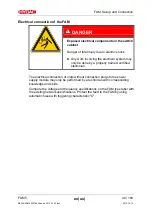
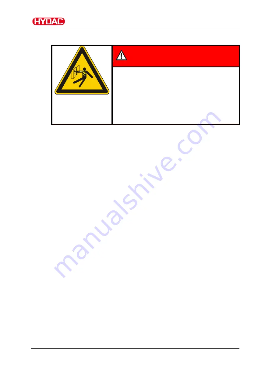
Electrical connection of the FAM 


 DANGER 

Exposed electrical components in the switch 
cabinet 

Danger of fatal injury due to electric shock 


Any work involving the electrical system may 

only be done by a properly trained, certified 
electrician.


The electrical connection of units without connection plugs to the power 
supply module may only be performed by a technician with corresponding 
knowledge and skills. 
Compare the voltage and frequency specifications on the FAM type label with 
the existing network specifications. Protect the feed to the FAM by using 
automatic fuses with triggering characteristic "C". 


Содержание FAM-5-M-2-A-05-R-H-B-Z-1

Страница 1: ...FAM 5 FluidAqua Mobil Operating and Maintenance Instructions English translation of original operating instructions Documentation no 3667663b ...

Страница 2: ...e Mr Günter Harge c o HYDAC International GmbH Industriegebiet 66280 Sulzbach Saar Telephone 49 0 6897 509 1511 Telefax 49 0 6897 509 1394 E Mail guenter harge hydac com HYDAC FILTER SYSTEMS GMBH All rights reserved No part of this work may be reproduced in any form print photocopy or by other means or processed duplicated or distributed using electronic systems without the written consent of the ...

Страница 3: ... of the safety information and instructions 11 Observe regulatory information 11 Proper Designated Use 12 Improper use or use deviating from intended use 12 Qualifications of personnel target group 14 Wear suitable clothing 16 Stoppage in an emergency EMERGENCY STOP 16 Unpacking the FAM 16 Transporting the FAM 17 Horizontal transport 18 Vertical transport 19 Transport suspended on a crane 20 Check...

Страница 4: ...Operating Elements on the FAM 42 Starting up the unit 44 Starting unit 44 Setting the underpressure in the vacuum column 45 Switching on the heater Checking setting optional 46 Venting the filter housing 47 Stopping switching off unit 48 Troubleshooting 50 Signal lamp Fault Unit off lights up 50 Performing maintenance 54 Maintenance intervals 54 Check fault signal lamps 57 Empty oil pan 57 Emptyin...

Страница 5: ...ance optional 81 Inspecting Cleaning the heating element 81 Removing Installing the heating element 82 Resetting the safety thermostat 84 Checking the AquaSensor AS1000 86 Checking the float switch in the oil pan 86 Spare parts 87 FAM 87 Fluid filter OLF 5 10 87 Vacuum pump 87 heater 88 Contact Service 89 Storing the FAM Taking it out of Operation 90 Disposing of the FAM 90 Technical Data 91 Conne...

Страница 6: ... which it is designed Keep this documentation in the vicinity of the product for immediate reference Note that the information on the unit s engineering contained in the documentation was that available at the time of publication Consequently there might be deviations in technical details illustrations and dimensions If you discover errors while reading the documentation or have suggestions or oth...

Страница 7: ...ct e g purchasing options etc may result in the information in the operating instructions no longer being completely accurate or sufficient When making modifications or performing repair work to components affecting the safety of the product the product may not be put back into operation until it has been examined and released by a HYDAC representative Please notify us immediately of any modificat...

Страница 8: ...future WHAT do I want to know I determine which topic I am looking for WHERE can I find the information I m looking for The document has a table of contents at the beginning I select the chapter I m looking for and the corresponding page number The documentation number with its index enables you to order another copy of the operating and maintenance instructions The index is incremented every time...

Страница 9: ...vices are present Secure the hazardous areas which may arise between the unit and other equipment Maintain the unit inspection intervals prescribed by law Document the results in an inspection certificate and keep it until the next inspection Hazard symbols These symbols are listed for all safety information and instructions in these operating instructions which indicate particular hazards to pers...

Страница 10: ...fety information and instructions DANGER DANGER indicates a danger with a high risk and which will lead to death or serious injury if not avoided WARNING WARNING indicates a danger with a medium risk and which can lead to death or serious injury if not avoided CAUTION CAUTION indicates a danger with a low risk and which can lead to minor injury if not avoided NOTICE NOTE indicates a danger which w...

Страница 11: ...icate the severity of the danger Warning instructions listed before an activity are laid out as follows SIGNAL WORD Type and source of danger Consequence of the danger HAZARD SYMBOL Measures to avert danger Observe regulatory information Observe the following regulatory information and guidelines Legal and local regulations for accident prevention Legal and local regulations for environmental prot...

Страница 12: ...ating medium Sealing material Hoses FAM xx M Mineral oil tested with mineral oil Mineral oils acc to DIN 50524 Gear oils according to DIN 51517 51524 Other hydraulic and lubrication oils which require or are compatible with NBR seals NBR NBR FAM xx I Insulation oil checked with e g Shell Diala Mineral oils acc to DIN 50524 Gear oils according to DIN 51517 51524 Other hydraulic and lubrication oils...

Страница 13: ...onsidered intended use HYDAC Filter Systems GmbH will assume no liability for any damage resulting from such use The user alone shall assume any and all associated risk Improper use may result in hazards and or will damage the unit Examples of improper use Operation in potentially explosive atmospheres Operation with a non approved fluid Operation under non approved conditions Operation when the s...

Страница 14: ...d several years work experience They are able to assess and perform the work assigned to them they are also able to recognize potential hazards Activity Person Knowledge Transport storage Forwarding agent Specialist personnel Proof of knowledge of cargo securing instructions Safe handling operation of hoisting and lifting equipment Hydraulic electrical installation first commissioning maintenance ...

Страница 15: ...Safety information FAM 5 en us 15 100 BEWA FAM5 3667663b en us 2012 12 12 doc 2012 12 12 Knowledge about reuse ...

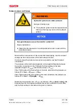
Страница 16: ...ety shoes Stoppage in an emergency EMERGENCY STOP In the event of an emergency turn the main switch by 90 in a counter clockwise direction to shut down the entire unit The entire unit downstream of this switch is voltage free and depressurized Normal pressure is restored to the vacuum column after 1 minute Unpacking the FAM Before delivery the FAM is inspected for leaks and proper functioning at t...

Страница 17: ...rovided for shifting Wind the suction and pressure hose and the connection cable around the holders provided for this purpose and either fasten them in place or remove the hoses from the FAM Move the FAM manually using the rollers Only ever use the FAM s handles to move it Before shifting the unit make sure to release the hand brake on the swivel casters Once the FAM is in the new desired position...

Страница 18: ...transport Completely empty the FAM as well as the vacuum pump before truck transport and close off all connections Close the air outlet of the vacuum pump using the matching suitable screw plugs Ensure the FAM is fixed tight to the car using load restraint belts at the suitable lashing points in the car ...

Страница 19: ...3b en us 2012 12 12 doc 2012 12 12 Vertical transport For transport by rail or truck supports must be placed under the mobile FAM so that none of the rollers are subjected to load pressure Secure the FAM with suitable belts Stationary version Mobile version ...

Страница 20: ...2 12 Transport suspended on a crane NOTICE Unsuitable lifting accessories The unit components will be damaged destroyed Use only suitable lifting accessories to raise or lash the FAM Make sure that the lifting accessories do not cause any force to be exerted on the components on the FAM ...

Страница 21: ...or the HYDAC department in charge The following items are included in the scope of delivery Qty Designation 1 FluidAqua Mobil 1 Key to the control cabinet 1 Vacuum pump oil 1 liter 1 Hose nipple with hose for emptying the vacuum pump 1 Suction and return hose only for mobile version FAM5 x 2 1 Operation and Maintenance Instructions this document 1 Electrical wiring diagram situated in the control ...

Страница 22: ...ter emulsified water and a large percentage of the water to be found in solution The integrated fluid filter ensures an efficient separation of solid particles Degassing of the medium is also achieved via the vacuum installed in the vacuum chamber FAM Versions Stationary FAM x 1 Mobil FAM x 2 In comparison to the stationary version the mobile version of the FAM also has 2x Wheels 2x Swivel casters...

Страница 23: ...nsformer oil The FAM5 is not suitable for online or onload operation 10 ppm The typical dewatering rate is up to 0 8l h at 1 10 000 ppm water content ISO VG32 50 C Dewatering performance Dewatering speed depends in particular on the oil type oil temperature oil quantity tank condition water content and the environmental conditions and can differ considerably from the indicated values depending on ...

Страница 24: ... with the tank volume Tank volume in liters Size 1 500 FAM 5 1 000 7 000 FAM 10 FAM 10 15 7 000 15 000 FAM 25 15 000 25 000 FAM 45 25 000 35 000 FAM 60 35 000 45 000 FAM 75 45 000 FAM 95 Note that free water e g on the bottom of the tank can have an influence on the entire water content in the system and thus on the length of time it takes to dewater Drain off free water completely ...

Страница 25: ...FAM Description FAM 5 en us 25 100 BEWA FAM5 3667663b en us 2012 12 12 doc 2012 12 12 FAM system components ...

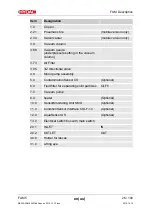
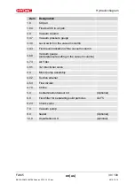
Страница 26: ...ting in the vacuum column 3 73 Air Filter 3 85 3 2 directional valve 4 0 Motor pump assembly 5 0 ContaminationSensor CS Optional 6 0 Fluid filter for separating solid particles OLF5 7 0 Vacuum pump 8 0 heater Optional 10 0 SensorMonitoring Unit SMU Optional 11 0 ConditionSensor Interface CSI F 10 Optional 12 0 AquaSensor AS Optional 13 0 Electrical switch box with main switch 20 1 INLET IN 20 2 OU...

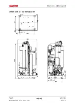
Страница 27: ...Dimensions stationary unit FAM 5 en us 27 100 BEWA FAM5 3667663b en us 2012 12 12 doc 2012 12 12 Dimensions stationary unit ...

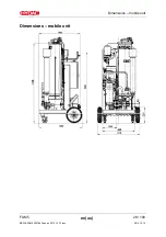
Страница 28: ...Dimensions mobile unit FAM 5 en us 28 100 BEWA FAM5 3667663b en us 2012 12 12 doc 2012 12 12 Dimensions mobile unit ...

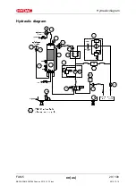
Страница 29: ...Hydraulic diagram FAM 5 en us 29 100 BEWA FAM5 3667663b en us 2012 12 12 doc 2012 12 12 Hydraulic diagram ...

Страница 30: ...e vacuum column 3 43 Fluid level indication of the vacuum column 3 68 Vacuum gauge underpressure setting in the vacuum column 3 73 Air Filter 3 85 3 2 directional valve 4 0 Motor pump assembly 4 02 Suction strainer 4 54 Flow divider 4 70 Orifice 5 0 ContaminationSensor CS Optional 6 0 Fluid filter for separating solid particles OLF5 6 23 Check valve 7 0 Vacuum pump 8 0 heater Optional 12 0 AquaSen...

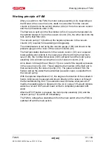
Страница 31: ...ects in the lower area After reaching the maximum level 3 38 the 3 2 directional valve 3 85 will switch and the motor pump assembly 4 0 will start sucking the oil out of vacuum column 3 0 Air is drawn in through the air filter 3 73 as a result of the negative pressure in the vacuum column 3 0 This air absorbs the moisture of the fluid and is then sucked out by the vacuum pump 7 0 The gases removed...

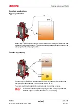
Страница 32: ...line and switch it on The permanent bypass purification means you always get optimum purity results Transfer by pumping Connect up the FAM to a contaminated oil tank by means of a suction line and pump the fluid into the clean oil tank via the FAM To avoid overfilling the tank B permanently monitor the oil level In order to achieve optimum purity results always operate the FAM in bypass current af...

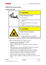
Страница 33: ...he unit Observe the following points when setting up the unit Place the unit on a horizontal and level surface Special mounting is not required Keep an area of at least 0 8 m around the unit free for maintenance purposes Mobile version only Lock the immobilization brakes on the wheels to avoid unintended movement rolling away of the unit Position the unit in the immediate vicinity of the tank to b...

Страница 34: ...2 doc 2012 12 12 Air coming out of the vacuum pump can contain particles of vacuum pump oil and or the fluid Depending on the composition of the oil and the composition of the gas there is a danger of damage to health if the emergent gas is inhaled over an extended period of time ...

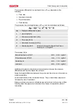
Страница 35: ... cross section of the inlet outlet port sizes In order to keep the pressure loss as low as possible use few threaded connections The pressure at the inlet outlet depends on the height differential between the suction connection on the FAM and the fluid surface in the tank aspiration height P height and the line losses P line If the FAM is above the fluid surface in the tank determine the pressure ...

Страница 36: ...l based hydraulic fluid has a density of 0 9 kg dm The density D is Mineral hydraulic oil HLP 0 85 0 90 kg dm Phosphate ester HFD R 1 00 1 10 kg dm Insulating oil 0 90 1 00 kg dm Lubricant 0 90 0 95 kg dm Additional threaded connections and pipe bends increase the pressure differential and must be taken into account Keep the height difference between the pump and the oil level in the tank as small...

Страница 37: ...in suction screen Never suck in free water The greatest contamination is found on the bottom of the tank All impurities like water or solid particles are deposited on the bottom of the tank Drain out the deposited free water at the bottom of the tank The suction pressure at the FAM inlet must be 0 2 bar Use a negative pressure resistant flexible hose or a pipe for the suction side connection Note ...

Страница 38: ...ures at the outlet are in open position each time before start up To prevent air from entering the medium make sure that the pressure hose with lance is always below the oil level in operation Take care to ensure that the maximum pressure of 2 bar is not exceeded at the outlet Preparing the Vacuum Pump After delivery transport by car check the vacuum pump for the following points and prepare it ac...

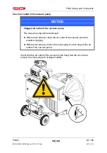
Страница 39: ...outlet of the vacuum pump The vacuum pump will be destroyed Before each startup check the air outlet of the vacuum pump for possible clogging Before each startup remove the screw plug or other clogs at the air outlet of the vacuum pump Check that the air outlet of the vacuum pump freely lets the air out and remove the screw plugs for transport safety ...

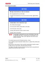
Страница 40: ...ing the electrical system may only be done by a properly trained certified electrician The electrical connection of units without connection plugs to the power supply module may only be performed by a technician with corresponding knowledge and skills Compare the voltage and frequency specifications on the FAM type label with the existing network specifications Protect the feed to the FAM by using...

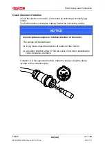
Страница 41: ...quires a clockwise rotating field at the connecting socket NOTICE Incorrect phase sequence rotation direction of the motor The pumps will be destroyed In jog mode check the direction of rotation of the motors A rotation direction arrow on the fan cover of the motor identifies the correct direction of rotation If rotation is in the opposite direction rotate the phases using the phase inverter in th...

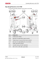
Страница 42: ...rating elements can be found on the FAM Item Designation 3 37 Underpressure display 3 48 Ball valve for emptying the vacuum column 3 68 Throttle valve for vacuum in the vacuum column 7 27 Ball valve for emptying filling the vacuum pump 8 0 Heater thermostat optional 10 0 SensorMonitoring Unit SMU optional 13 0 Main switch on off switch signal lamp ...

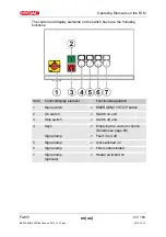
Страница 43: ...e the following functions Item Control display element Function designation 1 Main switch EMERGENCY STOP button 2 On switch Switch on unit 3 Stop switch Switch off unit 4 Keys Emptying the vacuum column Details see page 60 Signal lamp Fault Unit off 5 Signal lamp Unit switched on 6 Signal lamp Filter contaminated 7 Signal lamp optional Heater switched on ...

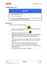
Страница 44: ...art up the unit by pressing the on switch 3 Depending on the filling level in the vacuum column the motor pump assembly 4 0 starts to suck either from the vacuum column or the tank via the suction strainer 4 02 and the 3 2 directional valve 3 85 The flow rate is split up in the flow divider 4 54 One part is funneled to the vacuum column 3 0 the other back to the tank via the fluid filter 6 0 The v...

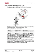
Страница 45: ...raulic oil 50 mm s 0 6 bar 400 mbar absolute Lubricant 300 mm s 0 4 bar 600 mbar absolute Some oils foam intensively when they enter the vacuum chamber This effect is particularly pronounced with high water or gas contents This effect is also to be observed with older oils or extremely high viscosity media If too much foam is caused it is drawn in by the vacuum pump In this case reduce the vacuum ...

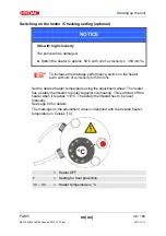
Страница 46: ...performance switch on the heater even with oils of a viscosity 350 mm s Set the desired heater temperature using the adjustment wheel The heater has a safety thermostat to protect against overheating This switches off the heater when it reaches 110 C The safety thermostat has to be reset manually See page 84 for details The markings on the adjustment wheel correspond with the desired heater temper...

Страница 47: ...leeding NOTICE Air in the fluid filter The filter element is not utilized completely Bleed the fluid filter after each shut down filter element replacement Bleed the fluid filter through the air bleed screw X until fluid comes out To do so slightly unscrew the air bleed screw X in the cover counterclockwise using an SW 6 mm Allen wrench Tighten the bleed screw X clockwise after venting ...

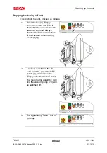
Страница 48: ...acuum column and hold it down until the vacuum column has been emptied Always observe the fill level indication of the vacuum column during the emptying 2 If no fluid is visible in the fill level indicator press the OFF button 3 and release the Empty vacuum column button The motor pump assembly 4 0 and the vacuum pump 7 0 will be switched off 3 The signal lamp Fault Unit off lights up ...

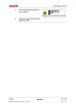
Страница 49: ...Starting up the unit FAM 5 en us 49 100 BEWA FAM5 3667663b en us 2012 12 12 doc 2012 12 12 4 Then switch off the unit at the main switch 1 5 Close all valves at the inlet and outlet IN OUT ...

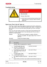
Страница 50: ...tarted using the on button after being started with the main switch or if the unit switches off automatically after three seconds in operation a fault is present Cause The unit cannot be started or switches off after 3 seconds in operation The signal lamp Fault Unit off lights up Remedy Perform the following steps Step Description 1 Start the FAM by pressing the on switch a The FAM starts and runs...

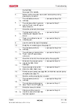
Страница 51: ...tely 10 Empty the oil collecting pan See page 57 a The unit starts and runs normally proceed to Step 100 11 b The unit does not start and the Fault Unit off signal lamp comes on proceed to Step 12 12 Check the oil level in the vacuum pump See page 66 a Oil level in the vacuum pump outside the MIN MAX markings proceed to Step 14 13 b Vacuum pump oil level OK Within the MIN MAX mark proceed to Step ...

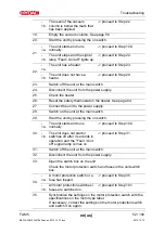
Страница 52: ... page 84 27 Connect the unit to the power supply 28 Switch on the unit at the main switch 29 Start the unit by pressing the on switch a The unit starts and runs normally proceed to Step 100 30 b The unit does not start or switches off after 3 seconds in operation and the Fault Unit off signal lamp comes on proceed to Step 31 31 Switch off the unit at the main switch 32 Disconnect the unit from the...

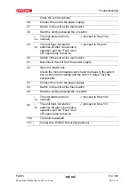
Страница 53: ...0 40 Switch off the unit at the main switch 41 Disconnect the unit from the power supply 42 Open the switch box Check the motor protection switch and the fuses in the switch box as well as the cabling and the motor in detail Test the components 43 Connect the unit to the power supply 44 Switch on the unit at the main switch 45 Start the unit by pressing the on switch a The unit starts and runs nor...

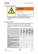
Страница 54: ...nance works listed here are necessary conditions for ensuring both long service life and error free operation of the FAM In addition you will find further information in the operating manuals published by the manufacturers of the components which are supplied with the FAM See page 24 hours daily 500 hours monthly 3000 hours every six months 6000 hours annually FAM Check the FAM for any leaks visua...

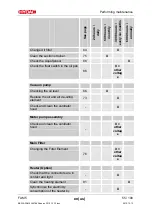
Страница 55: ...ck the float switch in the oil pan 86 X other voltag e Vacuum pump Checking the oil level 66 X Replace the oil and air de oiling element 73 X Check and clean the ventilator hood X Motor pump assembly Check and clean the ventilator hood X other voltag e Main Filter Changing the Filter Element 76 X other voltag e Heater Option Check that the connectors are in contact and tight X Clean the heating el...

Страница 56: ...electricity consumption of the motors by comparing the nominal values on the type labels X Perform an electrical safety inspection in accordance with DIN VDE 0702 and or corresponding national regulation X other voltag e Replace all hoses no later than after 5 years Perform the following work as needed FAM For details see page Empty oil pan 57 Empty vacuum columns 58 Emptying the heater 62 All pic...

Страница 57: ...012 12 12 Check fault signal lamps To check the fault signal lamp switch on the FAM at the main switch The signal lamp Fault Unit off then lights up Empty oil pan Empty the oil collection pan by opening the screw plug X Dispose of the draining oil in an environmentally friendly manner ...

Страница 58: ...ing the ball valve or with the pump To do this proceed as follows Empty vacuum column using the ball valve Make sure that a suitable container is available Open the ball valve and collect the fluid that comes out Once no more fluid escapes close the ball valve Fill the oil back into the tank or dispose of it in an environmentally friendly manner ...

Страница 59: ...63b en us 2012 12 12 doc 2012 12 12 Check the level in the vacuum column via the fill level display If no fluid is visible in the fill level indicator close the ball valve Fill the oil back into the tank or dispose of it in an environmentally friendly manner ...

Страница 60: ... vacuum column via the pump proceed as follows 1 If the unit is switched off switch on the unit at the main switch 1 2 Start the unit by switching it on at the on switch 2 Press the key 4 Empty vacuum column and hold it down until the vacuum column has been emptied Always observe the fill level indication of the vacuum column during the emptying 3 If no fluid is visible in the fill level indicator...

Страница 61: ...enance FAM 5 en us 61 100 BEWA FAM5 3667663b en us 2012 12 12 doc 2012 12 12 4 The signal lamp Fault Unit off lights up 5 Then switch off the unit at the main switch 1 6 Close all valves at the inlet and outlet IN OUT ...

Страница 62: ...l the oil back into the tank or dispose of it in an environmentally friendly manner To empty the heater proceed as follows 1 Stop the unit at the off switch and switch off the FAM at the main switch 2 Pull out the plug Disconnect the FAM from the power supply 3 Allow the heater to cool down 4 Always drain the vacuum column first See page 58 for details ...

Страница 63: ...he drain screw clockwise out of the heater 6 Collect the escaping fluid in a suitable container Fill the oil back into the tank or dispose of it in an environmentally friendly manner 7 Screw the drain plug counterclockwise into the filter bowl and tighten it firmly 8 Emptying the heater is now complete ...

Страница 64: ...months If the FAM is in a very dusty damp environment the replacement intervals shorten accordingly To replace the air filter proceed as follows 1 Unscrew the air filter 3 73 by hand counterclockwise 2 Dispose of the used air filter in an environmentally friendly manner 3 Screw in the new air filter 3 73 clockwise by hand and tighten it only by hand ...

Страница 65: ... pump possesses the components described below Item Designation a Oil filler neck c Oil drain d Oil sight glass g Oil separator h Suction port connection i Air vent k Safety screw on the plug l Plug for the level sensor m Level switch in the vacuum pump The following descriptions are in reference to these positions ...

Страница 66: ...N 51506 Group VDL ISO VG100 Check the oil level before start up topping up with vacuum pump oil if necessary Check the oil fill level of the vacuum pump on a monthly basis If necessary fill up with vacuum pump oil Max capacity is approx 0 3 liters The level switch monitors the oil level of the vacuum pump in operation If the fill level reaches the MIN MAX level it will switch off and the signal la...

Страница 67: ...uum pump oil in accordance with DIN 51506 Group VDL ISO VG100 when topping up Vacuum pump oil is available from HYDAC under the following part no Description Part no Vacuum pump oil VE101 DIN 51506 Group VDL ISO VG100 synthetic 1 liters 06018128 Vacuum pump oil VE101 DIN 51506 Group VDL ISO VG100 synthetic 5 liters 06018129 ...

Страница 68: ...p distant from hot surfaces Allow the vacuum pump to cool down before performing any work Proceed as follows to fill the vacuum pump 1 Switch the unit off at the main switch and unplug the power connector Allow the vacuum pump to cool down 2 Remove the threaded coupling k for the plug at the level switch Remove the plug I for the level switch in an upward direction ...

Страница 69: ...he vacuum pump by turning counterclockwise using a 24 mm open ended wrench Carefully remove the level switch from the vacuum pump in an upward direction 4 Fill the vacuum pump with vacuum pump oil VE 101 via the filler neck a 5 Check the oil level through the inspection glass d Fill the vacuum pump to no higher than the MAX mark ...

Страница 70: ... the vacuum pump from above To facilitate installation lift up the lower float Screw the level switch m into the vacuum pump by turning clockwise using a 24 mm open ended wrench and tighten it 7 Insert the plug l into the level switch and secure it by tightening the threaded coupling k 8 The vacuum pump filling is complete ...

Страница 71: ... FAM 5 en us 71 100 BEWA FAM5 3667663b en us 2012 12 12 doc 2012 12 12 Emptying the vacuum pump WARNING Hot surfaces Risk of burns Keep distant from hot surfaces Allow the vacuum pump to cool down before performing any work ...

Страница 72: ...il 3 Unscrew the screw plug from the drain fitting 4 Screw the hose nipple with hose onto the drain fitting Place the hose in the container and hold it securely during the entire process 5 Open the ball valve and allow the vacuum pump oil to drain completely 6 Once no more vacuum pump oil escapes close the ball valve 7 Unscrew the hose nipple with hose from the drain fitting 8 Screw the screw plug...

Страница 73: ...Switch off the FAM at the main switch Wait until the pressure in the vacuum column has reached atmospheric pressure 1000 mbar absolute To perform these tasks you will need the following tools and equipment Compressor oil VE101 for part no see replacement parts list To change the oil on the vacuum pump proceed as follows 1 Empty the vacuum pump as described on page 71 2 Remove the old oil filter an...

Страница 74: ... the oil separator g 6 Make sure that the new air deoiling element is provided with a new O ring 7 Install the air de oiling element in such a way that the opening is situated correctly in the holder in the oil separator g 8 Ensure that the tip of the screw in the middle of the filter spring protrudes approx 2 5 thread turns out of the filter spring 9 Install the filter spring in such a way that t...

Страница 75: ...ted at the pump inlet Clean the suction strainer at regular intervals To disassemble install the suction strainer proceed as follows 1 2 3 1 Unscrew the screw plug 1 counterclockwise with an open jaw wrench 2 Remove strainer insert 3 3 Clean the strainer insert flush it out and then blow flush it using compressed air 4 Check strainer insert 3 and sealing ring 2 on the screw plug for damage Replace...

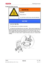
Страница 76: ...owing back out of the tank Make sure that the unit cannot be inadvertently switched back on during maintenance work 2 Put a suitable container 1 in place to catch exiting medium Depressurize the filter housing Carefully open the drain plug 2 on the filter bowl and empty the filter housing completely using the drain screw SW 6mm on the bottom of the filter housing The volume is 2 liters After drain...

Страница 77: ...maintenance FAM 5 en us 77 100 BEWA FAM5 3667663b en us 2012 12 12 doc 2012 12 12 4 Pull the filter bowl including filter element downwards 5 Remove 2 the filter element from the filter bowl by turning slightly 1 ...

Страница 78: ...c 2012 12 12 6 Clean the inside of the filter bowl of dirt and deposits 7 Check the O ring on the filter bowl for damage Replace it if necessary Moisten the O ring on the filter bowl with the operating medium 8 Moisten the O rings on the new filter element with the operating medium ...

Страница 79: ...s 79 100 BEWA FAM5 3667663b en us 2012 12 12 doc 2012 12 12 9 Turning it slightly press the new filter element down into the mount on the filter bowl 10 Push the filter bowl with the filter element up into the mount on the filter head ...

Страница 80: ...he bead on the filter bowl filter head Tighten the housing clamp with an Allen wrench SW 6mm in a clockwise direction The tightening torque is 5 Nm 12 Check that the drain plug on the filter bowl is secure 13 The filter element change is now complete Bleed the filter housing as described on page 47 After commissioning check the filtration unit for leaks ...

Страница 81: ...arly inspect and clean the heating element Inspecting Cleaning the heating element NOTICE Layer of film on the heating element The heating element will be destroyed Clean the heating element annually If the heating element is covered in a layer of film this will prevent the heat from being transferred to the oil and may cause the heating element to burn out and power requirements to increase Clean...

Страница 82: ...e the two covering stoppers of the screw holes 7 Unscrew and remove the two screws Torx 20 8 Disconnect all electrical connections to the heater and pull the cable from the cable fittings This work may only be done by authorized technical staff 9 Rotate the heating element counterclockwise out of the sheathing using a fork wrench SW 65 mm 10 Pull the heating element up and out of the sheath 11 Cle...

Страница 83: ...hten it 17 Insert all cabling through the cable fittings and attach all electrical connections to the heater This work may only be done by authorized technical staff 18 Attach the cover to the heater Screw in both screws Torx 20 and tighten them firmly 19 Attach the setting switch and the two covering stoppers for the screw holes 20 Plug the mains plug or connect the FAM up to the main electricity...

Страница 84: ...e heater 1 Stop the unit at the off switch and switch off the FAM at the main switch 2 Pull out the plug Disconnect the FAM from the power supply 3 Let the unit FAM and the heater cool down 4 Pull the setting switch of the heater up and off And remove the two covering stoppers of the screw holes 5 Unscrew and remove the two screws Torx 20 6 Pull the upper heater part up and out 7 Press the pin lev...

Страница 85: ...ght by screwing in the two screws 10 Attach the setting switch of the heater onto the shaft from above Note that the adjustment switch only fits one way onto the shaft 11 Plug the mains plug or connect the FAM up to the main electricity supply 12 Switch on the FAM at the main switch and start the unit by pressing the on switch ...

Страница 86: ...t set instruction manual Replace the AquaSensor if it exhibits great deviations Checking the float switch in the oil pan Proceed as follows to test the float switch 1 Use your fingers to raise the float switch in the oil pan 2 The FAM must shut down after 3 seconds and the Fault Unit off signal lamp comes on 3 Release the float switch and acknowledge the fault message by pressing the key 4 The FAM...

Страница 87: ...ner insert 250µm 1x sealing ring 6033967 1 Vacuum pressure gauge 639989 1 3 2 directional valve 3595115 1 Pressure hose Length 5 m 6013308 1 Suction hose Length 5 m 6004781 1 Level sensor vacuum chamber 1204801 available on request Fluid filter OLF 5 10 Quantit y Designation Part no 1 Filter element filtration rating 2 µm N5DM002 349494 1 Filter element filtration rating 5 µm N5DM005 3068101 1 Fil...

Страница 88: ...ing and draining hose 1 Ball valve for draining 551093 1 Service kit vacuum pump consisting of exhaust filter and seals 6014161 1 Vacuum pump oil VE101 1 liter 6018128 1 Vacuum pump oil VE101 5 liter 6018129 available on request heater Quantit y Designation Part no 1 O ring for housing 1 Adjustment switch 1 Seals available on request ...

Страница 89: ... 509 1174 Telefax 49 0 6897 509 846 E Mail filtersystems hydac com Regular inspection and maintenance work is indispensable for ensuring trouble free operation and long service life for your FluidAqua Mobil Our HYDAC Servicenter offers you these tasks within agreed upon time frames and at fixed prices HYDAC SERVICE GMBH Friedrichstaler Straße 15a Werk 13 66540 Neunkirchen Heinitz Germany Telephone...

Страница 90: ...ng it into storage as described under maintenance Pull out the power plug and securely fasten the hoses and power cord to the unit Store the unit in a clean dry non condensing space Observe the storage temperature range of 20 60 C Disposing of the FAM Please dispose of the packaging material in an environmentally friendly manner After dismantling the unit and separating the various materials dispo...

Страница 91: ...he unit when the filter is clogged Pump type Rotary vane vacuum pump Pump type Filling Draining Gear pump Operating pressure 0 8 bar 0 116 psi Permissible suction pressure at suction port 0 2 1 bar 2 9 14 5 psi Permissible Operating viscosity range 15 350 mm s without integrated heater 15 550 mm s with integrated heater Permissible viscosity range for the particle measurement 15 200 mm s with tech...

Страница 92: ...ominal voltage Length of connection hoses 5 m only in mobile version Material hoses see model code Hydraulic connectors See Connection Overview table on page 93 Empty weight 120 kg Noise level according to VBG121 70 dB A at 1 m distance Achievable residual water content 100 ppm Hydraulic and lube oils 50 ppm Turbine oils ISO VG 32 46 10 ppm Transformer oils ...

Страница 93: ...r 42L M52x2 external thread 2 Adapter Adapter G1 A external thread 3 FAM outlet connector 28L M36x2 external thread 4 Adapter Adapter G1 A external thread 5 Suction hose connection 42L M52x2 internal thread 6 Adapter Adapter G1 A external thread 7 Pressure hose connection 28L M36x2 internal thread 8 Adapter Adapter G1 A external thread ...

Страница 94: ...responds to ISO 12151 Form S Series L Stud end according to ISO 1179 2 Form E Output drive type N according to ISO 8434 4 Series L corresponding to ISO 12151 Form SWS Series L Contained within the scope of supply of the stationary FAM items 1 4 In the scope of supply of the mobile FAM you also receive with the connection hoses the items 5 8 ...

Страница 95: ...Ph PE 1 K 480 V 60 Hz 3 Ph PE 1 M 230 V 50 Hz 1 Ph PE O 460 V 60 Hz 3 Ph PE 1 P 230 V 60 Hz 1 Ph PE S 380 V 50 Hz 3 Ph PE AD 220 V 60 Hz 3 Ph PE X other voltage Filter size fluid filter 05 OLF 5 Vacuum pump R Rotary vane vacuum pump heater Z without heater H Heater for 200 359 V 1 kW for 360 690 V 2 4 kW Control concept B Basic Instrumentation Z none A AquaSensor AS C ContaminationSensor CS ACS Aq...

Страница 96: ...below Any modification of this product that is not coordinated with us in writing will cause this declaration to lose its validity Designation FluidAqua Mobil Type FAM 5 Series Part no Serial no EU Machinery Directive 2006 42 EC EU Electrical Equipment Regulations 2006 95 EC EU Directive on Electromagnetic Compatibility 2004 108 EC Safety of machinery and devices EN 12100 1 2 2012 05 30 Dr Andreas...

Страница 97: ... us 97 100 BEWA FAM5 3667663b en us 2012 12 12 doc 2012 12 12 Index A AquaSensor 26 Ausschalter 43 C ContaminationSensor 26 D Drosselventil 42 E Einschalter 43 S SensorMonitoring Unit 26 V Vakuumpumpe Luftaustritt 39 ...

Страница 98: ......

Страница 99: ......

Страница 100: ...iet Postfach 1251 66280 Sulzbach Saar 66273 Sulzbach Saar Germany Germany Phone 49 0 6897 509 01 Central Fax 49 0 6897 509 846 Technical Department Fax 49 0 6897 509 577 Sales Department Internet www hydac com E Mail filtersystems hydac com ...

Отзывы: