


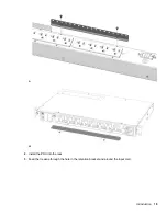


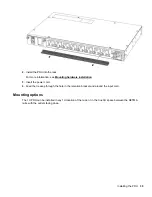
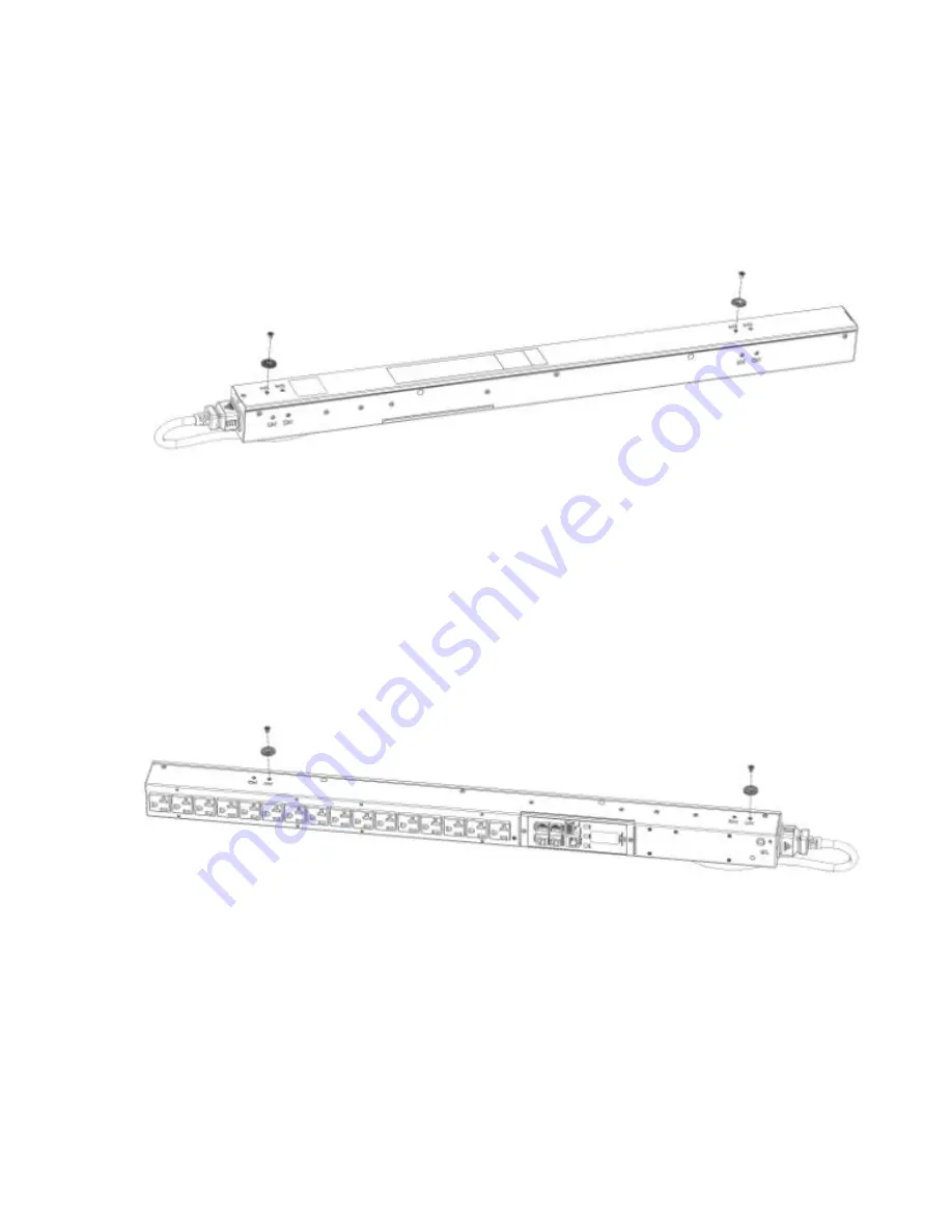
Installing the mounting hardware
To assist with mounting in non-HPE racks, each vertical PDU has two mounting hole locations (M1 and M2)
on the sides and back of the PDU for installing the buttons. When installing the mounting buttons, use either
the M1 or M2 mounting holes as a set.
Installing the mounting button–outlets facing the center of the rack
Procedure
1.
Align and install the mounting buttons in the screw holes on the face opposite of the receptacles.
2.
Install the PDU by inserting the mounting buttons in the keyhole slots on the PDU mounting bracket in the
rack.
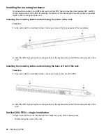
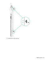
Installing the mounting button–outlets facing the back or front of the rack
Procedure
1.
Align and install the mounting buttons in the screw holes on the side of the PDU.
2.
Install the PDU by inserting the mounting buttons in the keyhole slots on the PDU mounting bracket in the
rack.
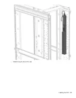
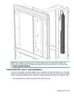
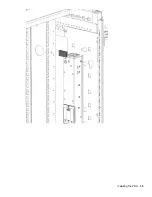
Vertical (0U) PDU—single installation
A single Vertical PDU can be installed with the outlets facing one of the following ways:
• Outlets facing the center of the rack
24
Installing the PDU
Содержание HPE G2 Series
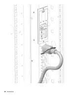
Страница 16: ...3 Secure the tie wrap 16 Introduction ...
Страница 20: ...20 Introduction ...
Страница 23: ...Installing the PDU 23 ...
Страница 25: ... Outlets facing the back of the rack Installing the PDU 25 ...
Страница 26: ... Outlets facing the front of the rack 26 Installing the PDU ...
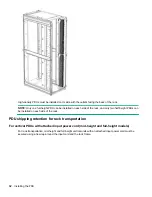
Страница 28: ... Two mid height PDUs with outlets facing towards the center of the rack 28 Installing the PDU ...
Страница 29: ... Four half height PDUs with outlets facing towards the center of the rack Installing the PDU 29 ...
Страница 31: ... Half height Installing the PDU 31 ...
Страница 34: ...2 Place the locking tape directly above the unit on the rack PDU mounting bracket 34 Installing the PDU ...
Страница 35: ...Installing the PDU 35 ...
Страница 37: ...2 Install the PDU in the rack frame Installing the PDU 37 ...
Страница 47: ...3 Install the PDU Installing the PDU 47 ...
Страница 49: ...Installing the PDU 49 ...
Страница 64: ...Web menu options Menu Illustration Overview Alarms 64 Remote configuration ...
Страница 65: ...Menu Illustration Help Table Continued Remote configuration 65 ...
Страница 66: ...Menu Illustration Language 66 Remote configuration ...
Страница 67: ...Menu Illustration Logs Remote configuration 67 ...
Страница 68: ...Menu Illustration Settings 68 Remote configuration ...
Страница 84: ...84 Remote configuration ...
Страница 92: ...92 Configuring local access ...
Страница 95: ...LED state Description Green red orange blinking Upgrading Off In USB mode OLED menu structure Local display 95 ...
Страница 99: ...Local display 99 ...
Страница 101: ...Local display 101 ...
Страница 107: ...Local display 107 ...
Страница 120: ...120 Connecting and configuring optional hardware ...
Страница 157: ...2 Pull out the Network Management Module from the PDU 3 Insert the new Network Management Module Appendix 157 ...
Страница 158: ...4 Align the Network Management Module and tighten the captive nuts by turning them clockwise 158 Appendix ...
Страница 160: ...3 Connect the ribbon cable to the replacement Network Management Module and the PDU 160 Appendix ...
Страница 161: ...4 Insert the replacement Network Management Module into the PDU and tighten the two screws Appendix 161 ...


