


Switched, and Metered & Switched Power Distribution Units are designed to collect a maximum of eight
environmental sensor measurements per PDU. For example, the Environmental 3-tempe 1-humidity
sensor (P9T02A) collects four sensor measurements. See the table for the number of sensor measurements
collected from each environmental sensor.
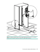
All HPE G2 Series Metered, Switched, and Metered & Switched Power Distribution Units have two physical
sensor ports, and each PDU can collect a total of eight sensor measurements (or readings). For example, if a
PDU has an Open/Close door sensor (P9T03A) and an Environmental 3-tempe 1-humidity sensor
(P9T02A) connected, both physical sensor ports are used with a total of five sensor measurements recorded.
Up to six physical sensors can be supported per PDU with the addition of the optional sensor port hub
(P9T07A).
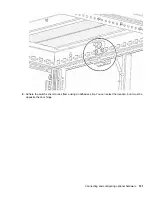
Figure 6: Sensor Ports for vertical PDU
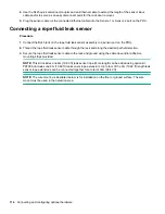
Connecting and configuring optional hardware
111
Содержание HPE G2 Series
Страница 16: ...3 Secure the tie wrap 16 Introduction ...
Страница 20: ...20 Introduction ...
Страница 23: ...Installing the PDU 23 ...
Страница 25: ... Outlets facing the back of the rack Installing the PDU 25 ...
Страница 26: ... Outlets facing the front of the rack 26 Installing the PDU ...
Страница 28: ... Two mid height PDUs with outlets facing towards the center of the rack 28 Installing the PDU ...
Страница 29: ... Four half height PDUs with outlets facing towards the center of the rack Installing the PDU 29 ...
Страница 31: ... Half height Installing the PDU 31 ...
Страница 34: ...2 Place the locking tape directly above the unit on the rack PDU mounting bracket 34 Installing the PDU ...
Страница 35: ...Installing the PDU 35 ...
Страница 37: ...2 Install the PDU in the rack frame Installing the PDU 37 ...
Страница 47: ...3 Install the PDU Installing the PDU 47 ...
Страница 49: ...Installing the PDU 49 ...
Страница 64: ...Web menu options Menu Illustration Overview Alarms 64 Remote configuration ...
Страница 65: ...Menu Illustration Help Table Continued Remote configuration 65 ...
Страница 66: ...Menu Illustration Language 66 Remote configuration ...
Страница 67: ...Menu Illustration Logs Remote configuration 67 ...
Страница 68: ...Menu Illustration Settings 68 Remote configuration ...
Страница 84: ...84 Remote configuration ...
Страница 92: ...92 Configuring local access ...
Страница 95: ...LED state Description Green red orange blinking Upgrading Off In USB mode OLED menu structure Local display 95 ...
Страница 99: ...Local display 99 ...
Страница 101: ...Local display 101 ...
Страница 107: ...Local display 107 ...
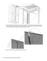
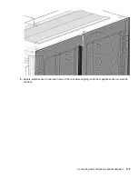
Страница 120: ...120 Connecting and configuring optional hardware ...
Страница 157: ...2 Pull out the Network Management Module from the PDU 3 Insert the new Network Management Module Appendix 157 ...
Страница 158: ...4 Align the Network Management Module and tighten the captive nuts by turning them clockwise 158 Appendix ...
Страница 160: ...3 Connect the ribbon cable to the replacement Network Management Module and the PDU 160 Appendix ...
Страница 161: ...4 Insert the replacement Network Management Module into the PDU and tighten the two screws Appendix 161 ...


