


HPE P/N
Form factor
14U
22U
36U
42U
47U
48U
P9S08A
0U—Half-height
2
2
4
4
4
P9S09A
0U—Mid-height
2
2
2
2
P9S12A
0U—Half-height
2
2
4
4
4
P9S14A
0U—Full-height
2
2
2
P9S17A
0U—Full-height
2
2
2
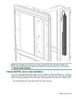
Switched 1U PDU (true 0U)—maximum configuration
Mounting configuration for a 1U PDU in an HPE 1075 mm rack depth between the RETMA rails. These are
the maximum number of PDUs per side of rack.
HPE P/N
Form factor
14U
22U
36U
42U
47U
48U
P9S07A
1U
1
2
2
6
6
6
P9S11A
1U
1
2
2
6
6
6
Metered & Switched PDUs—rack mounting options
HPE P/N
Form factor
0U (Vertical)
0U (between RETMA
rails)
U position in rack
P9S15A
0U—Full-height
*
P9S18A
0U—Full-height
*
P9S19A
0U—Full-height
*
P9S20A
0U—Full-height
*
P9S21A
0U—Full-height
*
P9S22A
0U—Full-height
*
P9S23A
0U—Full-height
high-density
*
P9S24A
0U—Full-height
*
P9S25A
0U—Full-height
high-density
*
HPE high-density model mounts on its side with outlets facing the back of the rack.
Metered & Switched 0U (Vertical) PDUs—maximum configuration
Mounting configuration for 0U (vertical) PDUs in an HPE 1075 mm rack depth. These are the maximum
number of PDUs per side of rack.
HPE P/N
Form factor
14U
22U
36U
42U
47U
48U
P9S15A
0U—Full-height
2
2
2
P9S18A
0U—Full-height
2
2
2
P9S19A
0U—Full-height
2
2
2
Table Continued
Introduction
13
Содержание HPE G2 Series
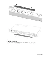
Страница 16: ...3 Secure the tie wrap 16 Introduction ...
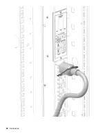
Страница 20: ...20 Introduction ...
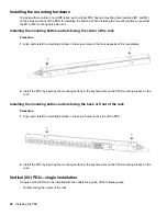
Страница 23: ...Installing the PDU 23 ...
Страница 25: ... Outlets facing the back of the rack Installing the PDU 25 ...
Страница 26: ... Outlets facing the front of the rack 26 Installing the PDU ...
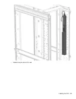
Страница 28: ... Two mid height PDUs with outlets facing towards the center of the rack 28 Installing the PDU ...
Страница 29: ... Four half height PDUs with outlets facing towards the center of the rack Installing the PDU 29 ...
Страница 31: ... Half height Installing the PDU 31 ...
Страница 34: ...2 Place the locking tape directly above the unit on the rack PDU mounting bracket 34 Installing the PDU ...
Страница 35: ...Installing the PDU 35 ...
Страница 37: ...2 Install the PDU in the rack frame Installing the PDU 37 ...
Страница 47: ...3 Install the PDU Installing the PDU 47 ...
Страница 49: ...Installing the PDU 49 ...
Страница 64: ...Web menu options Menu Illustration Overview Alarms 64 Remote configuration ...
Страница 65: ...Menu Illustration Help Table Continued Remote configuration 65 ...
Страница 66: ...Menu Illustration Language 66 Remote configuration ...
Страница 67: ...Menu Illustration Logs Remote configuration 67 ...
Страница 68: ...Menu Illustration Settings 68 Remote configuration ...
Страница 84: ...84 Remote configuration ...
Страница 92: ...92 Configuring local access ...
Страница 95: ...LED state Description Green red orange blinking Upgrading Off In USB mode OLED menu structure Local display 95 ...
Страница 99: ...Local display 99 ...
Страница 101: ...Local display 101 ...
Страница 107: ...Local display 107 ...
Страница 120: ...120 Connecting and configuring optional hardware ...
Страница 157: ...2 Pull out the Network Management Module from the PDU 3 Insert the new Network Management Module Appendix 157 ...
Страница 158: ...4 Align the Network Management Module and tighten the captive nuts by turning them clockwise 158 Appendix ...
Страница 160: ...3 Connect the ribbon cable to the replacement Network Management Module and the PDU 160 Appendix ...
Страница 161: ...4 Insert the replacement Network Management Module into the PDU and tighten the two screws Appendix 161 ...


