


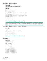


dev outlet <PDUID> status
Description
Query all outlet status with specified PDUID.
Example
HPE>Dev outlet 1 status
E000
Relay outlet status
Outlet#1: Close Outlet#2: Close Outlet#3: Close
Close
Outlet#4: CLose
Outlet#5: Close Outlet#6: Close Outlet#7: Close
Outlet#8: Close
Outlet#9 Close Outlet#10: Close Outlet#11:
Close
Outlet#12: Close
NOTE:
This command is invalid for Metered PDUs.
NOTE:
PDUIDs increment from 1. If in daisy chain mode, the master PDUID is 1 and the slave PDUIDs are 2
and 3.
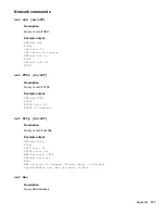
dev outlet <PDUID> <outlet index> [on|off]
Description
Query or set specified PDUID and outlet status.
Example
HPE>Dev outlet 1 1 off
E000
NOTE:
This command is invalid for Metered PDUs.
dev sensor
Description
List all sensors equipped.
Example output
HPE>dev sensor
E000
Sensor count 4
-----------------
Name Type, SN Value
T1, TEMP 012345678 27.5
T3, TEMP 012345678 27.2
T2, TEMP 012345678 27.3
RH HUMI 012345678 44
140
Appendix
Содержание HPE G2 Series
Страница 16: ...3 Secure the tie wrap 16 Introduction ...
Страница 20: ...20 Introduction ...
Страница 23: ...Installing the PDU 23 ...
Страница 25: ... Outlets facing the back of the rack Installing the PDU 25 ...
Страница 26: ... Outlets facing the front of the rack 26 Installing the PDU ...
Страница 28: ... Two mid height PDUs with outlets facing towards the center of the rack 28 Installing the PDU ...
Страница 29: ... Four half height PDUs with outlets facing towards the center of the rack Installing the PDU 29 ...
Страница 31: ... Half height Installing the PDU 31 ...
Страница 34: ...2 Place the locking tape directly above the unit on the rack PDU mounting bracket 34 Installing the PDU ...
Страница 35: ...Installing the PDU 35 ...
Страница 37: ...2 Install the PDU in the rack frame Installing the PDU 37 ...
Страница 47: ...3 Install the PDU Installing the PDU 47 ...
Страница 49: ...Installing the PDU 49 ...
Страница 64: ...Web menu options Menu Illustration Overview Alarms 64 Remote configuration ...
Страница 65: ...Menu Illustration Help Table Continued Remote configuration 65 ...
Страница 66: ...Menu Illustration Language 66 Remote configuration ...
Страница 67: ...Menu Illustration Logs Remote configuration 67 ...
Страница 68: ...Menu Illustration Settings 68 Remote configuration ...
Страница 84: ...84 Remote configuration ...
Страница 92: ...92 Configuring local access ...
Страница 95: ...LED state Description Green red orange blinking Upgrading Off In USB mode OLED menu structure Local display 95 ...
Страница 99: ...Local display 99 ...
Страница 101: ...Local display 101 ...
Страница 107: ...Local display 107 ...
Страница 120: ...120 Connecting and configuring optional hardware ...
Страница 157: ...2 Pull out the Network Management Module from the PDU 3 Insert the new Network Management Module Appendix 157 ...
Страница 158: ...4 Align the Network Management Module and tighten the captive nuts by turning them clockwise 158 Appendix ...
Страница 160: ...3 Connect the ribbon cable to the replacement Network Management Module and the PDU 160 Appendix ...
Страница 161: ...4 Insert the replacement Network Management Module into the PDU and tighten the two screws Appendix 161 ...


