


Values Displayed
Navigation
Serial
dev sensor
[pduID]
SNMp
pdu3TemperatureScale
pdu3TemperatureTable
• Current temperature readings are displayed on the
•
Connecting a temperature sensor
Procedure
1.
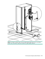
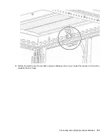
Secure the sensor to the perforated area on the rack enclosure door by threading the provided cable tie
through the recessed channel in the sensor box and through the door.
2.
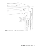
Secure the RJ45 cable along the desired path to the PDU using the remaining cable ties.
3.
Use the RJ45 quick disconnect coupler and an Ethernet cable to extend the length of the sensor input
cable and/or to serve as an easy disconnect point for the rack door removal.
4.
Plug the sensor cable, or the connected Ethernet cable, into the Sensor-1 or Sensor-2 port on the PDU or
into the sensor port hub, if applicable.
Connecting a temperature and humidity sensor
Procedure
1.
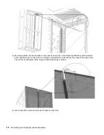
Secure the sensor to the perforated area on the rack enclosure door by threading the provided cable tie
through the recessed channel in the sensor box and through the door.
2.
Secure the RJ45 cable along the desired path to the PDU using the remaining cable ties.
3.
Use the RJ45 quick disconnect coupler and an Ethernet cable to extend the length of the sensor input
cable and/or to serve as an easy disconnect point for the rack door removal.
4.
Plug the sensor cable (or the connected Ethernet cable) into the Sensor-1 or Sensor-2 port on the PDU or
into the sensor port hub, if applicable.
Connecting a 3-temperature and 1-humidity sensor
Procedure
1.
Secure the sensor to the perforated area on the rack enclosure door by threading the provided cable tie
through the recessed channel in the sensor box and through the door.
2.
Secure the RJ45 cable along the desired path to the PDU using the remaining cable ties.
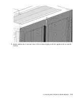
3.
Secure the two additional temperature probes near the top and the bottom of the perforated rack enclosure
door using the cable ties provided.
Connecting and configuring optional hardware
113
Содержание HPE G2 Series
Страница 16: ...3 Secure the tie wrap 16 Introduction ...
Страница 20: ...20 Introduction ...
Страница 23: ...Installing the PDU 23 ...
Страница 25: ... Outlets facing the back of the rack Installing the PDU 25 ...
Страница 26: ... Outlets facing the front of the rack 26 Installing the PDU ...
Страница 28: ... Two mid height PDUs with outlets facing towards the center of the rack 28 Installing the PDU ...
Страница 29: ... Four half height PDUs with outlets facing towards the center of the rack Installing the PDU 29 ...
Страница 31: ... Half height Installing the PDU 31 ...
Страница 34: ...2 Place the locking tape directly above the unit on the rack PDU mounting bracket 34 Installing the PDU ...
Страница 35: ...Installing the PDU 35 ...
Страница 37: ...2 Install the PDU in the rack frame Installing the PDU 37 ...
Страница 47: ...3 Install the PDU Installing the PDU 47 ...
Страница 49: ...Installing the PDU 49 ...
Страница 64: ...Web menu options Menu Illustration Overview Alarms 64 Remote configuration ...
Страница 65: ...Menu Illustration Help Table Continued Remote configuration 65 ...
Страница 66: ...Menu Illustration Language 66 Remote configuration ...
Страница 67: ...Menu Illustration Logs Remote configuration 67 ...
Страница 68: ...Menu Illustration Settings 68 Remote configuration ...
Страница 84: ...84 Remote configuration ...
Страница 92: ...92 Configuring local access ...
Страница 95: ...LED state Description Green red orange blinking Upgrading Off In USB mode OLED menu structure Local display 95 ...
Страница 99: ...Local display 99 ...
Страница 101: ...Local display 101 ...
Страница 107: ...Local display 107 ...
Страница 120: ...120 Connecting and configuring optional hardware ...
Страница 157: ...2 Pull out the Network Management Module from the PDU 3 Insert the new Network Management Module Appendix 157 ...
Страница 158: ...4 Align the Network Management Module and tighten the captive nuts by turning them clockwise 158 Appendix ...
Страница 160: ...3 Connect the ribbon cable to the replacement Network Management Module and the PDU 160 Appendix ...
Страница 161: ...4 Insert the replacement Network Management Module into the PDU and tighten the two screws Appendix 161 ...


