


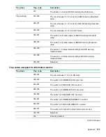


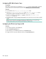

Trap Codes assigned to Alarms List
Trap codes assigned for critical alarms
Trap class
Trap code
Description
1
The PDU unit active power is ABOVE critical threshold value.
2
The PDU unit active power is BELOW critical threshold value.
3
The phase 1 voltage is ABOVE critical threshold value.
4
The phase 2 voltage is ABOVE critical threshold value.
5
The phase 3 voltage is ABOVE critical threshold value.
6
The phase 1 voltage is BELOW critical threshold value.
7
The phase 2 voltage is BELOW critical threshold value.
8
The phase 3 voltage is BELOW critical threshold value.
9
The phase 1 current is ABOVE critical threshold value.
10
The phase 2 current is ABOVE critical threshold value.
11
The phase 3 current is ABOVE critical threshold value.
12
The phase 1 current is BELOW critical threshold value.
13
The phase 2 current is BELOW critical threshold value.
Trap critical
14
The phase 3 current is BELOW critical threshold value.
15-26
The circuit breaker (1~12) current is ABOVE critical threshold
value.
27-38
The circuit breaker (1~12) current is BELOW critical threshold
value.
39-50
The circuit breaker (1~12) is in OFF state.
51-98
The outlet (1~48) active power is ABOVE critical threshold
value.
99-146
The outlet (1~48) active power is BELOW critical threshold
value.
Table Continued
Appendix
153
Содержание HPE G2 Series
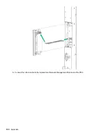
Страница 16: ...3 Secure the tie wrap 16 Introduction ...
Страница 20: ...20 Introduction ...
Страница 23: ...Installing the PDU 23 ...
Страница 25: ... Outlets facing the back of the rack Installing the PDU 25 ...
Страница 26: ... Outlets facing the front of the rack 26 Installing the PDU ...
Страница 28: ... Two mid height PDUs with outlets facing towards the center of the rack 28 Installing the PDU ...
Страница 29: ... Four half height PDUs with outlets facing towards the center of the rack Installing the PDU 29 ...
Страница 31: ... Half height Installing the PDU 31 ...
Страница 34: ...2 Place the locking tape directly above the unit on the rack PDU mounting bracket 34 Installing the PDU ...
Страница 35: ...Installing the PDU 35 ...
Страница 37: ...2 Install the PDU in the rack frame Installing the PDU 37 ...
Страница 47: ...3 Install the PDU Installing the PDU 47 ...
Страница 49: ...Installing the PDU 49 ...
Страница 64: ...Web menu options Menu Illustration Overview Alarms 64 Remote configuration ...
Страница 65: ...Menu Illustration Help Table Continued Remote configuration 65 ...
Страница 66: ...Menu Illustration Language 66 Remote configuration ...
Страница 67: ...Menu Illustration Logs Remote configuration 67 ...
Страница 68: ...Menu Illustration Settings 68 Remote configuration ...
Страница 84: ...84 Remote configuration ...
Страница 92: ...92 Configuring local access ...
Страница 95: ...LED state Description Green red orange blinking Upgrading Off In USB mode OLED menu structure Local display 95 ...
Страница 99: ...Local display 99 ...
Страница 101: ...Local display 101 ...
Страница 107: ...Local display 107 ...
Страница 120: ...120 Connecting and configuring optional hardware ...
Страница 157: ...2 Pull out the Network Management Module from the PDU 3 Insert the new Network Management Module Appendix 157 ...
Страница 158: ...4 Align the Network Management Module and tighten the captive nuts by turning them clockwise 158 Appendix ...
Страница 160: ...3 Connect the ribbon cable to the replacement Network Management Module and the PDU 160 Appendix ...
Страница 161: ...4 Insert the replacement Network Management Module into the PDU and tighten the two screws Appendix 161 ...


