background image


81 

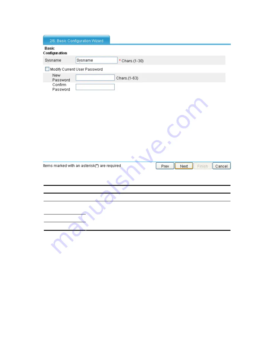
Figure 53


Basic configuration wizard: 2/6 (basic information) 


Table 2


Basic information configuration items 

Item Description 

Sysname 

Set the system name. 

Modify Current User 
Password 

New Password 

Confirm Password 

Specify whether to modify the login password of the current user. 
To modify the password of the current user, set the new password and the confirm 

password, and the two passwords must be identical. 


Configuring service management 

Click 

Next

 on the basic information configuration page to enter the service management page, as shown 

in 

Figure 54

Содержание A-F5000

Страница 1: ...HP High End Firewalls Getting Started Guide Part number 5998 2626 Software version A F1000 E Firewall module R3166P13 A F5000 A5 R3206P14 Document version 6PW100 20110909 ...

Страница 2: ... MATERIAL INCLUDING BUT NOT LIMITED TO THE IMPLIED WARRANTIES OF MERCHANTABILITY AND FITNESS FOR A PARTICULAR PURPOSE Hewlett Packard shall not be liable for errors contained herein or for incidental or consequential damages in connection with the furnishing performance or use of this material The only warranties for HP products and services are set forth in the express warranty statements accompa...

Страница 3: ...al 19 Logging in through Telnet 21 Introduction 21 Telnet login authentication modes 21 Configuring none authentication for Telnet login 22 Configuring password authentication for Telnet login 23 Configuring scheme authentication for Telnet login 24 Configuring common settings for VTY user interfaces optional 27 Configuring the device to log in to a Telnet server as a Telnet client 29 Logging in t...

Страница 4: ...all module from the network device 73 Logging in to the firewall module from the network device 73 Configuring the AUX user interface of the firewall module 73 Logging in to the firewall module 73 Monitoring and managing the firewall module on the network device 74 Resetting the system of the firewall module 74 Configuring the ACSEI protocol 74 Example for monitoring and managing the firewall modu...

Страница 5: ...iguring local users 108 Local user overview 108 User levels 108 Configuring a local user 108 Local user configuration example 109 Configuring user login control 110 User login control overview 110 Configuring login control over Telnet users 110 Configuring source IP based login control over NMS users 113 Configuring source IP based login control over web users 114 Displaying online users 116 Overv...

Страница 6: ...mmand levels 130 Introduction 130 Configuring a user privilege level 130 Switching user privilege level 133 Modifying the level of a command 134 Saving the current configuration 134 Displaying and maintaining CLI 134 Support and other resources 135 Contacting HP 135 Subscription service 135 Related information 135 Documents 135 Websites 135 Conventions 136 Index 138 ...

Страница 7: ...dium sized networks It supports the following functions Traditional firewall functions Virtual firewall security zone attack protection URL filtering Application Specific Packet Filter ASPF which can monitor connection processes and user operations and provide dynamic packet filtering together with ACLs Multiple types of VPN services such as IPsec VPN RIP OSPF BGP routing Power supply redundancy b...

Страница 8: ... F5000 supports the following functions and features Protection against external attacks internal network protection traffic monitoring email filtering web filtering application layer filtering ASPF Multiple types of VPN services such as L2TP VPN GRE VPN IPsec VPN and dynamic VPN RIP OSPF BGP routing routing policy and policy based routing Power supply 1 1 redundancy backup AC AC or DC DC Service ...

Страница 9: ...t Filter ASPF which can monitor connection processes and user operations and provide dynamic packet filtering together with ACLs Multiple types of VPN services such as IPsec VPN RIP OSPF BGP routing A firewall module provides two GE ports and two GE combo interfaces It is connected to the main network device through the internal 10GE port The HP main network device s rear card has the line speed f...

Страница 10: ...hysical ports to security zones and the firewall module adds logical interfaces subinterfaces and VLAN interfaces of the 10 GE port to security zones Configurations for interface based security functions are the same on the two firewalls The difference is that the A F1000 E supports these functions on physical ports and the firewall module support these functions on the logical interfaces of the 1...

Страница 11: ...ity and abundant port features It can be deployed at the egress of a network to protect security for the internal network You can deploy two firewalls to implement stateful failover Active active stateful failover can balance user data Active standby stateful failover improves availability of the firewalls They back up each other to avoid a single point failure Figure 7 Network diagram for the A F...

Страница 12: ...ules can protect against external attacks and implement security access control of the internal network by using security zones You can meet the development of the network simply by installing more firewall modules to a switch or router Deploying two switches routers with the firewall modules in the network can improve service availability Figure 8 Network diagram for the firewall module applicati...

Страница 13: ...efault the IP address of the management Ethernet interface is 192 168 0 1 24 Configure the authentication mode of VTY login users scheme by default Configure the user privilege level of VTY login users 0 by default Logging in through SSH By default you cannot log in to a device through SSH To do so log in to the device through the console port and complete the following configuration Enable the SS...

Страница 14: ...nfigure SNMP basic parameters User interface overview User interfaces or lines allow you to manage and monitor sessions between the terminal and device when you log in to the device through the console port AUX port or through Telnet or SSH Asynchronous serial interfaces include the following types Synchronous asynchronous serial interface operating in asynchronous mode whose interface index begin...

Страница 15: ...the user interface view takes effect The user interface varies depending on the login method and the login time Numbering user interfaces User interfaces can be numbered by using absolute numbering or relative numbering Absolute numbering Absolute numbering identifies a user interface or a group of different types of user interfaces The specified user interfaces are numbered from number 0 with a s...

Страница 16: ...ge and maintain the device Therefore you need to perform configurations to increase device security and manageability Logging in through the console port Introduction Logging in through the console port is the most common login method and is also the first step to configure other login methods By default you can log in to a device through its console port only After logging in to the device throug...

Страница 17: ...ice first plug the DB 9 connector of the console cable into the PC and then plug the RJ 45 connector of the console cable into your device To disconnect the PC from the device first unplug the RJ 45 connector and then the DB 9 connector 2 Launch a terminal emulation program such as HyperTerminal in Windows XP The following takes the HyperTerminal of Windows XP as an example Select a serial port to...

Страница 18: ...12 Figure 10 Connection description Figure 11 Specify the serial port used to establish the connection ...

Страница 19: ...ted to press Enter if the device successfully completes the power on self test POST A prompt such as HP appears after you press Enter as shown in Figure 13 Figure 13 Configuration page 4 Execute commands to configure the device or check the running status of the device To get help type ...

Страница 20: ...see Configuring none authentication for console login Configure to authenticate users by using the local password Password Set the local password For more information see Configuring password authentication for console login Configure the authentication scheme Configure a RADIUS HWTACACS scheme Configure the AAA scheme used by the domain Remote AAA authenticati on Configure the username and passwo...

Страница 21: ...ngs for console login Optional See Configuring common settings for console login optional After the configuration the next time you log in to the device through the console port you are prompted to press enter A prompt such as HP appears after you press Enter as shown in Figure 14 Figure 14 Configuration page Configuring password authentication for console login Configuration prerequisites You hav...

Страница 22: ...ion and have user privilege level 3 after login Set the local password set authentication password cipher simple password Required By default no local password is set Configure common settings for console login Optional See Configuring common settings for console login optional When you log in to the device through the console port after configuration you are prompted to enter a login password A p...

Страница 23: ...nds on the user privilege level A user is authorized a command level not higher than the user privilege level With command authorization enabled the command level for a login user is determined by both the user privilege level and AAA authorization If a user executes a command of the corresponding command level the authorization server checks whether the command is authorized If yes the command ca...

Страница 24: ...n Optional See Configuring common settings for console login optional After you enable command authorization or command accounting you need to perform the following configuration to make the function take effect Create a HWTACACS scheme and specify the IP address of the authorization server and other authorization parameters Reference the created HWTACACS scheme in the ISP domain When users adopt ...

Страница 25: ...t number Configure the baud rate speed speed value Optional By default the transmission rate is 9600 bps Transmission rate is the number of bits that the device transmits to the terminal per second Configure the parity check mode parity even mark none odd space Optional none by default Configure console port properties Configure the stop bits stopbits 1 1 5 2 Optional By default the stop bits of t...

Страница 26: ...et the display type of both the device and the client to VT100 If the device and the client use different display types for example hyper terminal or Telnet terminal or both are set to ANSI when the total number of characters of the currently edited command line exceeds 80 an anomaly such as cursor corruption or abnormal display of the terminal display may occur on the client Configure the user pr...

Страница 27: ...tings Enable the Telnet client Telnet client Obtain the IP address of the management Ethernet interface on the server By default the device is disabled with the Telnet server and client functions On a device that serves as the Telnet client you can log in to a Telnet server to perform operations on the server On a device that serves as the Telnet server you can configure the authentication mode an...

Страница 28: ... HWTACACS scheme Configure the AAA scheme used by the domain Remote AAA authentication Configure the username and password on the AAA server Configure the authentication username and password Scheme Select an authenticatio n scheme Local authentication Configure the AAA scheme used by the domain as local For more information see Configuring scheme authentication for Telnet login Configuring none a...

Страница 29: ...ng steps You enter the VTY user interface as shown in Figure 18 If All user interfaces are used please try later is displayed it means the current login users exceed the maximum number Please try later Figure 18 Configuration page Configuring password authentication for Telnet login Configuration prerequisites You have logged in to the device By default you can log in to the device through the con...

Страница 30: ...users user privilege level level Required 0 by default Configure common settings for VTY user interfaces Optional See Configuring common settings for VTY user interfaces optional When you log in to the device through Telnet again perform the following steps You are required to enter the login password A prompt such as HP appears after you enter the correct password and press Enter as shown in Figu...

Страница 31: ...opted Enable command authorization command authorization Optional By default command authorization is not enabled Create a HWTACACS scheme and specify the IP address of the authorization server and other authorization parameters Reference the created HWTACACS scheme in the ISP domain Enable command accounting command accounting Optional By default command accounting is disabled The accounting serv...

Страница 32: ...ation or command accounting you need to perform the following configuration to make the function take effect Create a HWTACACS scheme and specify the IP address of the authorization server and other authorization parameters Reference the created HWTACACS scheme in the ISP domain When users adopt the scheme mode to log in to the device the level of the commands that the users can access depends on ...

Страница 33: ...mand Remarks Enter system view system view Enter management Ethernet interface view interface interface type interface number Specify an IP address for the management Ethernet interface ip address ip address mask mask length Required By default the IP address of the management Ethernet interface is 192 168 0 1 24 Return to system view quit Enable display of copyright information copyright info ena...

Страница 34: ...all user interfaces The system automatically terminates the user s connection if there is no information interaction between the device and the user in timeout time Setting idle timeout to 0 disables the timer User interface configuration Specify a command to be automatically executed when a user logs in to the current user interface auto execute command command Optional By default command auto ex...

Страница 35: ...d Remarks telnet remote host service port source interface interface type interface number ip ip address Configure the device to log in to a Telnet server as a Telnet client telnet ipv6 remote host i interface type interface number port number Required Use either command Available in user view Specify the source IPv4 address or source interface for sending Telnet packets telnet client source inter...

Страница 36: ...d for SSH login but no login password is configured so you cannot log in to the device through SSH by default Before you can log in to the device through SSH you need to log in to the device through the console port and configure the authentication mode user level and common settings This section includes these topics Configuring the SSH server Configuring the SSH client to log in to the SSH serve...

Страница 37: ...s that are supported by the device regardless of the command execution result This helps control and monitor user operations on the device If command accounting is enabled and command authorization is not enabled every executed command is recorded on the HWTACACS server If both command accounting and command authorization are enabled only the authorized and executed commands are recorded on the HW...

Страница 38: ...intenance Configuration Guide After you enable command authorization or command accounting you need to perform the following configuration to make the function take effect Create a HWTACACS scheme and specify the IP address of the authorization server and other authorization parameters Reference the created HWTACACS scheme in the ISP domain When users adopt the scheme mode to log in to the device ...

Страница 39: ...in user view NOTE You can configure other settings for the SSH client to work with the SSH server For more information see System Management and Maintenance Configuration Guide Logging in through the AUX port Introduction As shown in Figure 24 the console cable used in AUX port login is the same as that in console port login For a device that has separate console and AUX ports you can use both to ...

Страница 40: ...nd password The following table lists AUX port login configurations for different authentication modes Authentication mode Configuration Remarks None Configure not to authenticate users For more information see Configuring none authentication for AUX login Configure to authenticate users by using the local password Password Set the local password For more information see Configuring password authe...

Страница 41: ...ew system view Enter one or more AUX user interface view user interface aux first number last number Specify the none authentication mode authentication mode none Required By default password authentication is performed for users that log in through the AUX port Configure common settings for AUX login Optional See Configuring common settings for AUX login optional After the configuration next time...

Страница 42: ...ion mode password Required By default you can log in to the device through the AUX port with password authentication and have user privilege level 0 after login Set the local password set authentication password cipher simple password Required By default no local password is set Configure common settings for AUX login Optional See Configuring common settings for AUX login optional After the config...

Страница 43: ... command with the default level not higher than the user privilege level With the command authorization configured the command level for a login user is determined by both the user privilege level and AAA authorization If a user executes a command of the corresponding command level the authorization server checks whether the command is authorized If yes the command can be executed Enable command a...

Страница 44: ...ttings for AUX login Optional See Configuring common settings for AUX login optional After you enable command authorization or command accounting you need to perform the following configuration to make the function take effect Create a HWTACACS scheme and specify the IP address of the authorization server and other authorization parameters Reference the created HWTACACS scheme in the ISP domain Wh...

Страница 45: ...arity even mark none odd space Optional By default the parity check mode of the AUX port is set to none which means no check bit Configure the stop bits stopbits 1 1 5 2 Optional By default the stop bits of the AUX port is 1 Stop bits are the last bits transmitted in data transmission to unequivocally indicate the end of a character The more the bits are the slower the transmission is Configure AU...

Страница 46: ...e client Configure the user privilege level for login users user privilege level level Optional By default the default command level is 0 for the AUX user interface Set the maximum number of lines on the next screen screen length screen length Optional By default the next screen displays 24 lines at most A value of 0 disables the function Set the size of history command buffer history command max ...

Страница 47: ...erial port of a PC does not support hot swap so do not plug or unplug the console cable to or from the PC when your device is powered on To connect the PC to the device first plug the DB 9 connector of the console cable into the PC and then plug the RJ 45 connector of the console cable into your device To disconnect the PC from the device first unplug the RJ 45 connector and then the DB 9 connecto...

Страница 48: ...42 Figure 29 Connection description Figure 30 Specify the serial port used to establish the connection ...

Страница 49: ... enter the login password if the device successfully completes the power on self test POST A prompt such as HP appears after you press Enter as shown in Figure 32 Figure 32 Configuration page 4 Execute commands to configure the device or check the running status of the device To get help type ...

Страница 50: ...ly Administrator side The telephone number of the remote modem connected to the AUX port of the remote switch is obtained The AUX port is correctly connected to the modem Configurations have been configured on the modem The modem is connected to a telephone cable that works properly Device side Authentication configuration has been completed on the remote switch Login procedure 1 Set up a configur...

Страница 51: ...odem from response to commands and save the configuration To verify your configuration enter AT V to show the configuration results NOTE The configuration commands and the output for different modems may be different For more information see the user guide of your modem 4 Launch a terminal emulation utility such as HyperTerminal in Windows XP create a new connection the telephone number is the num...

Страница 52: ...46 Figure 34 Connection Description Figure 35 Enter the phone number ...

Страница 53: ...and device execute the ATH command on the terminal to terminate the connection between the PC and modem If you cannot execute the command on the terminal input AT and then press Enter When you are prompted OK execute the ATH command and the connection is terminated if OK is displayed You can also terminal the connection between the PC and device by clicking on the hyper terminal window Do not clos...

Страница 54: ... Configuration Remarks None Configure not to authenticate users For more information see Configuring none authentication for modem login Configure to authenticate users by using the local password Password Set the local password For more information see Configuring password authentication for modem login Configure the authentication scheme Configure a RADIUS HWTACACS scheme Configure the AAA schem...

Страница 55: ...y default the mode is flow Exit to system view quit Enter one or more AUX user interface views user interface aux first number last number Specify the none authentication mode authentication mode none Required By default the modem login authentication mode is password Configure common settings for VTY user interfaces Optional See Configuring common settings for VTY user interfaces optional After t...

Страница 56: ... aux interface number Specify operating mode for the AUX interface async mode flow protocol Required By default the mode is flow Exit to system view quit Enter one or more AUX user interface views user interface aux first number last number Specify the password authentication mode authentication mode password Required By default the modem login authentication mode is password Set the local passwor...

Страница 57: ...nterface is protocol Configuration procedure Follow these steps to configure scheme authentication for modem login To do Use the command Remarks Enter system view system view Enter AUX interface view interface aux interface number Specify operating mode for the AUX interface async mode flow protocol Required By default the mode is flow Exit to system view quit Enter AUX user interface view user in...

Страница 58: ...allows the HWTACACS server to record all executed commands that are supported by the device regardless of the command execution result This helps control and monitor user operations on the device If command accounting is enabled and command authorization is not enabled every executed command is recorded on the HWTACACS server If both command accounting and command authorization are enabled only th...

Страница 59: ...arameters Reference the created HWTACACS scheme in the ISP domain When users adopt the scheme mode to log in to the device the level of the commands that the users can access depends on the user privilege level defined in the AAA scheme When the AAA scheme is local the user privilege level is defined by the authorization attribute level level command When the AAA scheme is RADIUS or HWTACACS the u...

Страница 60: ...s 1 Stop bits are the last bits transmitted in data transmission to unequivocally indicate the end of a character The more the bits are the slower the transmission is Configure the data bits databits 5 6 7 8 Optional By default the data bits of the AUX port is 8 Data bits is the number of bits representing one character The setting depends on the contexts to be transmitted For example you can set ...

Страница 61: ...een length screen length Optional By default the next screen displays 24 lines at most A value of 0 disables the function Set the size of the history command buffer history command max size value Optional By default the buffer saves 10 history commands at most Set the idle timeout timer idle timeout minutes seconds Optional The default idle timeout is 10 minutes The system automatically terminates...

Страница 62: ... Display user interface information display user interface num1 aux console vty num2 summary Available in any view Display the configuration of the device when it serves as a Telnet client display telnet client configuration Available in any view Release a specified user interface free user interface num1 aux vty num2 Available in user view Multiple users can log in to the system to simultaneously...

Страница 63: ...erface sometimes you may be unable to open the web interface To avoid this problem turn off the Windows firewall before login If you log in to the device through the web interface after the software version of the device changes HP recommends you to delete the temporary Internet files on IE otherwise the web page content may not be displayed correctly Logging in to the firewall by using the defaul...

Страница 64: ...user userA servce type telnet HP luser userA password simple 123456 HP luser userA authorization attribute level 3 2 Add an interface into the management zone in hidden command line view to enable the firewall to communicate with a PC through this interface and then you can log in to the firewall through this interface HP _ Now you enter a hidden command view for developer s testing some commands ...

Страница 65: ...figuring HTTPS login Required to use one approach Install a web browser PC Obtain the IP address of the management Ethernet interface of the device Configuring HTTP login Follow these steps to configure HTTP login To do Use the command Remarks Enter system view system view Enable the HTTP service ip http enable Required Enabled by default Configure the HTTP service port number ip http port port nu...

Страница 66: ...with any SSL server policy If you disable the HTTPS service the system automatically de associates the HTTPS service from the SSL service policy Before re enabling the HTTPS service associate the HTTPS service with an SSL server policy first Any changes to the SSL server policy associated with the HTTP service that is enabled do not take effect Enable the HTTPS service ip https enable Required Dis...

Страница 67: ...uired By default the HTTPS service is not associated with any ACL Associating the HTTPS service with an ACL enables the device to allow only clients permitted by the ACL to access the device Create a local user and enter local user view local user user name Required By default no local user is configured Configure a password for the local user password cipher simple password Required By default no...

Страница 68: ...he console port and configure the IP address and mask of the management Ethernet interface GigabitEthernet 0 1 of the device Firewall system view Firewall interface GigabitEthernet0 1 Firewall GigabitEthernet0 1 ip address 10 153 17 82 255 255 255 0 Firewall GigabitEthernet0 1 quit Create a local user named admin and set the password to admin for the user Specify the Telnet service type for the lo...

Страница 69: ...ccessing the Device configure HTTPS login as follows Configure the Firewall as the HTTPS server and request a certificate for it The Host acts as the HTTPS client Request a certificate for it In this example Windows Server acts as the CA Install Simple Certificate Enrollment Protocol SCEP add on on the CA The name of the CA that issues certificates to the Firewall and Host is new ca Before perform...

Страница 70: ...ki domain 1 certificate request from ra Firewall pki domain 1 certificate request entity en Firewall pki domain 1 quit Create local RSA key pairs Firewall public key local create rsa Retrieve the CA certificate from the certificate issuing server Firewall pki retrieval certificate ca domain 1 Request a local certificate from a CA through SCEP for the Firewall Firewall pki request certificate domai...

Страница 71: ...ient On the host run the IE browser In the address bar enter http 10 1 2 2 certsrv and request a certificate for the host as prompted 3 Verify the configuration Enter https 10 1 1 1 in the address bar and select the certificate issued by new ca Then the web login page of the Firewall appears On the login page type the username usera and password 123 to enter the web management page NOTE To log in ...

Страница 72: ...elect a Web content zone to specify its security settings as shown in Figure 45 Figure 45 Internet Explorer setting I Click Custom Level and a dialog box Security Settings appears As shown in Figure 46 select the Enable button for Run ActiveX controls and plug ins Script ActiveX controls marked safe for scripting and Active scripting ...

Страница 73: ...xplorer setting II Click OK in the Security Settings dialog box Solution for Mozilla Firefox Open the Firefox Web browser and then select Tools Options Click the Content tab select the Enable JavaScript check box and click OK ...

Страница 74: ...68 Figure 47 Firefox web browser setting ...

Страница 75: ...ual of your NMS For a firewall module you need to configure its management Ethernet interface s IP address on the network device The firewall module and network device are integrated to work as one device From the perspective of an SNMP UDP domain based NMS however the network device and firewall module are separate SNMP agents They have different software systems and manage their own MIB objects ...

Страница 76: ...re an SNMP group and specify its access right snmp agent group v3 group name authentication privacy read view read view write view write view notify view notify view acl acl number Required By default no SNMP group is configured Add a user to the SNMP group snmp agent usm user v3 user name group name cipher authentication mode md5 sha auth password acl acl number Required If the cipher keyword is ...

Страница 77: ...iguration approach is for SNMPv3 NOTE The device supports three SNMP versions SNMPv1 SNMPv2c and SNMPv3 For more information about SNMP see System Management and Maintenance Configuration Guide NMS login example In this example IMC is used as the NMS for illustration 1 Configuration on the device Assign 1 1 1 1 24 for the IP address of device Make sure the device and the NMS can reach each other C...

Страница 78: ... device After the device is found you can manage and maintain the device through the IMC For example query device information or configure device parameters The SNMP settings on the IMC must be the same as those configured on the device If not the device cannot be found or managed by the IMC See the IMC manuals for more information Click Help in the upper right corner of each configuration page to...

Страница 79: ...view system view Enter AUX user interface view user interface aux first number last number Specify the none authentication mode authentication mode none Required By default the AUX user interface uses password authentication Configure the user privilege level user privilege level level Required 0 by default HP recommends you to set it to 3 Logging in to the firewall module Use the following comman...

Страница 80: ...Configuring the ACSEI protocol Introduction to ACSEI ACSEI is an HP proprietary protocol It provides a method for exchanging information between ACFP clients and ACFP server so that the ACFP server and clients can cooperate to run a service As a supporting protocol of ACFP ACSEI also has two entities server and client The ACSEI server is integrated into the software system Comware of the network d...

Страница 81: ...ent 2 Start up the network device and enable the ACSEI server function on it 3 The ACSEI client multicasts a registration request 4 After the ACSEI server receives a valid registration request it negotiates parameters with the ACSEI client and establishes a connection with the client if the negotiation succeeds 5 The ACSEI server and the ACSEI client mutually monitor the connection 6 Upon detectin...

Страница 82: ... On the firewall module Display current ACSEI client state display acsei client status Available in any view Example for monitoring and managing the firewall module from the network device Network requirements A firewall module is installed in slot 3 of the network device to detect the traffic passing the network device The internal interface Ten GigabitEthernet 3 0 1 on the network device is conn...

Страница 83: ...nected to OAP FIREWALL card 2 Configure the clock synchronization timer and the monitoring timer Configuration on the network device Enable ACSEI server Switch system view Switch acsei server enable Enter ACSEI server view Switch acsei server Set the clock synchronization timer to 10 minutes Switch acsei server acsei timer clock sync 10 Set the monitoring timer to 10 seconds Switch acsei server ac...

Страница 84: ...e firewall module on the network device 2 Display the ACSEI server configuration information on the network device Switch display current configuration configuration acsei server acsei server acsei timer clock sync 10 acsei timer monitor 10 return Switch The output shows that the clock synchronization timer and monitoring timer are 10 minutes and 10 seconds respectively ...

Страница 85: ...yer 3 Ethernet interfaces and VLAN interfaces For more information see Network Management Configuration Guide NAT Configure dynamic NAT internal server translation and related parameters For more information see NAT Configuration Guide Zone Configure a zone to perform interface or IP address based security policy control For more information see Access Control Configuration Guide This chapter desc...

Страница 86: ...2 Basic configuration wizard 1 6 Configuring the system name and user password Click Next on the first page of the basic configuration wizard to enter the basic information configuration page as shown in Figure 53 ...

Страница 87: ...assword New Password Confirm Password Specify whether to modify the login password of the current user To modify the password of the current user set the new password and the confirm password and the two passwords must be identical Configuring service management Click Next on the basic information configuration page to enter the service management page as shown in Figure 54 ...

Страница 88: ...n the device Disabled by default HTTP Specify whether to enable HTTP on the device and set the HTTP port number Disabled by default IMPORTANT If the current user has logged in to the web interface through HTTP disabling HTTP or modifying the HTTP port number will result in disconnection with the device therefore perform the operation with caution When you modify a port number ensure that the port ...

Страница 89: ...ault HTTPS uses the PKI domain default If this PKI domain does not exist the system will prompt you for it when the configuration wizard is completed however this will not affect the execution of other configurations Configuring the IP address for an interface Click Next on the service management configuration page to enter the interface IP address configuration page as shown in Figure 55 The tabl...

Страница 90: ...rface obtains an IP address automatically through the DHCP protocol Do not change The IP address of the interface does not change IP Address Mask If you select Stack Address as the approach for obtaining the IP address you need to set the interface IP address and network mask IMPORTANT Modification to the interface IP address will result in disconnection with the device so make changes with cautio...

Страница 91: ...server is enabled when a user from the external network accesses the internal server the NAT translates the destination address of request packets into the private IP address of the internal server when the internal server replies to the packets the NAT translates the source address private IP address of reply packets into a public IP address By default the internal server is disabled IMPORTANT Co...

Страница 92: ... page lists all configurations you have made in the basic configuration wizard Confirm the configurations To modify your configuration click Prev to go back to the previous page if no modification is needed click Finish to execute all configurations ...

Страница 93: ...ce The current system name is on the very top of the navigation tree as shown in Figure 58 Figure 58 Current system name Select Device Management Device Basic Device Basic Info from the navigation tree to enter the page as shown inFigure 59 Figure 59 Device basic information Configuring the device name in the CLI A device name identifies a device in a network If the device name is Sysname the prom...

Страница 94: ...rface System time overview System time allows you to display and set the device system time on the Web interface The device supports setting system time through manual configuration and automatic synchronization of NTP server time An administrator can by no means keep time synchronized among all the devices within a network by changing the system clock on each device because this is a huge amount ...

Страница 95: ...ough the calendar page You can perform the following operations on the calendar page Click Today to set the current date on the calendar to the current system date of the local host and the time keeps unchanged Set the year month date and time and then click OK After finishing the configuration in the calendar you must click Apply in the system time configuration page to save your configuration Co...

Страница 96: ... the stratum level of the local clock The stratum level of the local clock decides the precision of the local clock A higher value indicates a lower precision A stratum 1 clock has the highest precision and a stratum 16 clock is not synchronized and cannot be used as a reference clock Source Interface Set the source interface for an NTP message If you do not want the IP address of a certain interf...

Страница 97: ...ime to the NTP server You can configure two NTP servers The clients will choose the optimal reference source IMPORTANT The IP address of an NTP server is a unicast address and cannot be a broadcast or a multicast address or the IP address of the local clock source Date and time configuration example 1 Network requirements The local clock of Device A is set as the reference clock with the stratum o...

Страница 98: ...m the start time on the start date to the end time on the end date in this year Daylight saving time is the standard time plus the add time clock summer time zone name one off start time start date end time end date add time Set a daylight saving time scheme Adopt daylight saving time every year clock summer time zone name repeating start time start date end time end date add time Optional Use eit...

Страница 99: ...igured is the original system time summer offset Configure clock summer time ss one off 00 30 2005 1 1 1 00 2005 8 8 2 System time configured 03 00 00 ss Sat 01 01 2005 If the original system time summer offset is not in the daylight saving time range the system time configured is the original system time After this configuration if you disable the daylight saving the system time becomes the syste...

Страница 100: ...onfigured is the original system time zone offset Configure clock timezone zone time add 1 and clock summer time ss one off 1 00 2007 1 1 1 00 2007 8 8 2 System time configured 02 00 00 zone time Sat 01 01 2005 2 and 3 or 3 and 2 If the value of the original system time zone offset is in the summer time range the system time configured is the original system time zone offset summer offset Configur...

Страница 101: ...me summer offset If the value of date time summer offset is in the summer time range the system time configured is date time Configure clock timezone zone time add 1 clock summer time ss one off 1 00 2008 1 1 1 00 2008 8 8 2 and clock datetime 3 00 2008 1 1 System time configured 03 00 00 ss Tue 01 01 2008 Setting the idle timeout timer NOTE You can set the idle timeout timer in the web interface ...

Страница 102: ...console port AUX port or asynchronous serial interface The copyright information is displayed in the following format Copyright c 2004 2010 Hewlett Packard Development Company L P Without the owner s prior written consent no decompiling or reverse engineering shall be allowed When the display of copyright information is disabled the copyright information never appears Follow these steps to enable ...

Страница 103: ... a banner Single line input In single line input mode all banner information is input in the same line The start and end characters of the input text must be the same and are not part of the banner information The input text together with the command keywords cannot exceed 510 characters In this mode do not press Enter after typing the banner information For example to configure a banner like Have...

Страница 104: ...lease input banner content and quit with the character A System prompt Please input the Password A Configuring the maximum number of concurrent users Follow these steps to configure the maximum number of users that can enter the system view simultaneously To do Use the command Remarks Enter system view system view Configure the maximum number of concurrent users configure user count number Optiona...

Страница 105: ...that the current configuration is not saved in the configuration file to be used at next boot the system will prompt that the device cannot reboot Device reboot configuration example 1 Network requirements The IP address and mask of the interface on Device A and those of Host A are shown in Figure 66 It is required to reboot Device A through the Web interface on Host A Figure 66 Network diagram fo...

Страница 106: ...ble in user view CAUTION A device reboot interrupts ongoing services Use these commands with caution Before rebooting a device use the save command to save the current configurations Before rebooting a device use the display startup and display boot loader commands to check whether the configuration file and boot file to be used at the next boot are configured The precision of the reboot timer is ...

Страница 107: ...xecuted No Yes Can a task be saved No Yes NOTE The system does not check whether input view and command arguments are correct You must ensure their correctness Otherwise the specified commands in the scheduled task cannot be executed The system does not require your confirmation when it is executing a scheduled task If there is information for you to confirm the system automatically inputs Y or Ye...

Страница 108: ...off repeating at time month date month day week day week daylist command command Configure a command to be executed after a delay time time time id one off repeating delay time command command Required Use any of the commands If you use the time at command changing the system time will change the execution time of the scheduled task If you use the time delay command changing the system time will n...

Страница 109: ... Firewall job pc1 time 1 repeating at 8 00 week day mon tue wed thu fri command undo shutdown Configure the Firewall to shut down GigabitEthernet 0 1 at 18 00 on working days every week Firewall job pc1 time 2 repeating at 18 00 week day mon tue wed thu fri command shutdown Firewall job pc1 quit Create scheduled task pc2 and enter its view Firewall job pc2 Configure the task to be executed in the ...

Страница 110: ... Mondays Tuesdays Wednesdays Thursdays Fridays Time 2 Execute command shutdown at 18 00 Mondays Tuesdays Wednesdays Thursdays Fridays Job name pc3 Specified view GigabitEthernet 0 3 Time 1 Execute command undo shutdown at 08 00 Mondays Tuesdays Wednesdays Thursdays Fridays Time 2 Execute command shutdown at 18 00 Mondays Tuesdays Wednesdays Thursdays Fridays Configuring temperature alarm threshold...

Страница 111: ...mation is required when you execute this command If you fail to make a confirmation within 30 seconds or enter N to cancel the operation the command will not be executed Identifying and diagnosing pluggable transceivers Introduction to pluggable transceivers Table 9 lists of the commonly used pluggable transceivers They can be further divided into optical transceivers and electrical transceivers b...

Страница 112: ...or name or name of the vendor who customizes the transceiver Diagnosing a pluggable transceiver The system outputs alarm information for you to diagnose and troubleshoot faults of pluggable transceivers Optical transceivers customized by HP also support the digital diagnosis function which monitors the key parameters of a transceiver such as temperature voltage laser bias current TX power and RX p...

Страница 113: ... in any view Display the electrical label information display device manuinfo Available in any view Display the temperature information display environment cpu Available in any view Display fan operating states display fan fan id Available in any view Display memory usage display memory Available in any view Display the power state display power Available in any view Display state of the redundant...

Страница 114: ...onfigure and management Visitor Users of this level can only perform ping and traceroute operations They can neither access the data on the Firewall nor configure the Firweall Monitor Users of this level can perform ping and traceroute operations and access the data on the Firewall but cannot configure the Firewall Configure Users of this level can perform ping and traceroute operations access dat...

Страница 115: ...ncluding FTP SSH Telnet Terminal and PPP IMPORTANT For a user to log in to the Firewall through the web interface you must select the service type Telnet for the user Password Set the password Confirm Password Reset the password which must be the same with the previously set password Local user configuration example Network requirements As shown in Figure 70 configure a local user account on the f...

Страница 116: ...r ACL NMS Configuring source IP based login control over NMS users Basic ACL Web Configuring source IP based login control over web users Basic ACL Configuring login control over Telnet users Configuration preparation Before configuration determine the permitted or denied source IP addresses source MAC addresses and destination IP addresses Configuring source IP based login control over Telnet use...

Страница 117: ...s To do Use the command Remarks Enter system view system view Create an advanced ACL and enter its view or enter the view of an existing advanced ACL acl ipv6 number acl number match order config auto Required By default no advanced ACL exists Configure rules for the ACL rule rule id permit deny rule string Required Exit advanced ACL view quit Enter user interface user interface type first number ...

Страница 118: ...server are not in the same subnet Source MAC based login control configuration example 1 Network requirements As shown in Figure 71 configure an ACL on the Firewall to permit only Telnet packets sourced from Host A and Host B Figure 71 Network diagram for configuring source MAC based login control 2 Configuration procedure Create basic ACL 2000 and configure rule 1 to permit packets sourced from H...

Страница 119: ...ault no basic ACL exists Create rules for this ACL rule rule id permit deny source sour addr sour wildcard any time range time name fragment logging Required Exit the basic ACL view quit Configure an SNMP community associating the SNMP community with the ACL snmp agent community read write community name acl acl number Create an SNMP group associating the SNMP group with the ACL snmp agent group v...

Страница 120: ... the SNMP community and the SNMP group Firewall snmp agent community read aaa acl 2000 Firewall snmp agent group v2c groupa acl 2000 Firewall snmp agent usm user v2c usera groupa acl 2000 Configuring source IP based login control over web users Administrators can log in to the web management page of the firewall through HTTP or HTTPS to remotely manage the firewall By using the ACL you can control...

Страница 121: ...ers To do Use the command Remarks Log off online web users free web users all user id user id user name user name Required Execute the command in user interface view Source IP based login control over web users configuration example 1 Network requirements As shown in Figure 73 configure the Firewall to allow only web users from Host B to access Figure 73 Network diagram for configuring source IP b...

Страница 122: ...rs as shown in Figure 74 This list shows all current online users Figure 74 Online users Table 11 Fields of the online user list Field Description User ID Identity of the online user in the system User Name Username used for authentication IP Address IP address of the user s host User Type Type of the online user including PPP 8021X Portal GCM Admin Telnet L2TP MAC authentication and VoIP The webp...

Страница 123: ...devices provide multiple methods for entering the CLI such as through the console port through Telnet and through SSH For more information see Getting Started Guide Command conventions Command conventions help you understand command meanings Commands in HP product manuals comply with the conventions listed in Table 12 Table 12 Command conventions Convention Description Boldface The keywords of a c...

Страница 124: ...command as an example to understand the meaning of the command line parameters according to Table 12 Figure 76 Read command line parameters For example you can type the following command line at the CLI of your device and press Enter to set the device system time to 10 o clock 30 minutes 20 seconds February 23 2010 sysname clock datetime 10 30 20 2 23 2010 You can read any command that is more com...

Страница 125: ... and enter its view enter user interface view to configure login user attributes create a local user and enter local user view to configure the password and level of the local user and enter OSPF view to configure OSPF parameters NOTE Enter in any view to display all the commands that can be executed in this view Figure 77 Command line views Entering system view When you log in to the device you a...

Страница 126: ...view without using the quit command repeatedly You can also press Ctrl Z to return to user view from the current view Follow the step below to exit to user view To do Use the command Remarks Return to user view return Required Available in any view except user view Using the CLI online help Type a question mark to obtain online help See the following examples 1 Type in any view to display all comm...

Страница 127: ...mplete character string followed by a The CLI displays all commands starting with the typed character s sysname c cd clock cluster copy sysname display cl clipboard clock cluster Typing commands Editing command lines Table 13 lists some shortcut keys you can use to edit command lines Table 13 Editing functions Key Function Common keys If the edit buffer is not full pressing a common key inserts th...

Страница 128: ...eyword of a command with your preferred keyword For example if you configure show as the replacement for the display keyword then to execute the display xx command you can input the command alias show xx Note the following guidelines when configuring command aliases When you input a command alias the system displays and saves the command in its original format instead of its alias In other words y...

Страница 129: ...Table 14 for hotkeys reserved by the system NOTE By default the Ctrl G Ctrl L and Ctrl O hotkeys are associated with pre defined commands and the Ctrl T and Ctrl U hotkeys are not Ctrl G corresponds to the display current configuration command Ctrl L corresponds to the display ip routing table command Ctrl O corresponds to the undo debugging all command Table 14 Hotkeys reserved by the system Hotk...

Страница 130: ...ring to the right Esc N Moves the cursor down by one line available before you press Enter Esc P Moves the cursor up by one line available before you press Enter Esc Specifies the cursor as the beginning of the clipboard Esc Specifies the cursor as the ending of the clipboard NOTE The hotkeys in the table above are defined by the switch If the same hotkeys are defined by the terminal software that...

Страница 131: ...ncomplete command Ambiguous command found at position Ambiguous command Too many parameters Too many parameters Wrong parameter found at position Wrong parameters Using command history The CLI automatically saves the commands recently used in the history command buffer You can access and execute them again Accessing history commands Follow a step below to access history commands To do Use the key ...

Страница 132: ...y command max size command see Getting Started Guide Command Reference Configuring the history buffer size Follow these steps to configure the history buffer size To do Use the command Remarks Enter system view system view Enter user interface view user interface first num1 last num1 aux console tty vty first num2 last num2 Set the maximum number of commands that can be saved in the history buffer...

Страница 133: ... use or plus a regular expression to filter subsequent output information equals the keyword begin equals the keyword exclude and equals the keyword include The following definitions apply to the begin exclude and include keywords begin Displays the first line that matches the specified regular expression and all lines that follow exclude Displays all lines that do not match the specified regular ...

Страница 134: ...fied by the index A character string refers to the string within before index refers to the sequence number starting from 1 from left to right of the character group before If only one character group appears before index can only be 1 if n character groups appear before index index can be any integer from 1 to n For example string 1 repeats string and a matching string must contain stringstring s...

Страница 135: ...Display the configuration from the line containing user interface to the last line in the current configuration the output information depends on the device model and the current configuration Sysname display current configuration begin user interface user interface con 0 user interface aux 0 user interface vty 0 4 authentication mode none user privilege level 3 return 2 Example of using the exclu...

Страница 136: ...t this level will be restored to the default settings Commands at this level include debugging terminal refresh and send 2 System Provides service configuration commands including routing configuration commands and commands for configuring services at different network levels By default commands at this level include all configuration commands except for those at manage level 3 Manage Involves com...

Страница 137: ...l the user privilege level is 0 For remote authentication if you do not configure the user privilege level the user privilege level depends on the default configuration of the authentication server Example of configuring a user privilege level by using AAA authentication parameters You are required to authenticate the users that telnet to the switch through VTY 1 verify their username and password...

Страница 138: ...er interface user privilege level level Optional By default the user privilege level for users logged in through the console user interface is 3 and that for users logged in through the other user interfaces is 0 Follow these steps to configure the user privilege level under a user interface none or password authentication mode To do Use the command Remarks Enter system view system view Enter user...

Страница 139: ...d terminating the current connection After the privilege level switch users can continue to configure the switch without the need to re log in but the commands that they can execute have changed For example if the current user privilege level is 3 the user can configure system parameters After switching to user privilege level 0 the user can only execute simple commands like ping and tracert and o...

Страница 140: ... command level may bring inconvenience to your maintenance and operation or even potential security problems Saving the current configuration On the device you can input the save command in any view to save all the submitted and executed commands into the configuration file Commands saved in the configuration file can survive a reboot The save command does not take effect on one time commands such...

Страница 141: ... wwalerts After registering you will receive email notification of product enhancements new driver versions firmware updates and other product resources Related information Documents To find related documents browse to the Manuals page of the HP Business Support Center website http www hp com support manuals For related documentation navigate to the Networking section and select a networking categ...

Страница 142: ...eparated by vertical bars from which you select one choice multiple choices or none 1 n The argument or keyword and argument combination before the ampersand sign can be entered 1 to n times A line that starts with a pound sign is comments GUI conventions Convention Description Boldface Window names button names field names and menu items are in bold text For example the New User window appears cl...

Страница 143: ...ting capable device such as a router or Layer 3 switch Represents a generic switch such as a Layer 2 or Layer 3 switch or a router that supports Layer 2 forwarding and other Layer 2 features Port numbering in examples The port numbers in this document are for illustration only and might be unavailable on your device ...

Страница 144: ... 134 Displaying and maintaining CLI login 56 Displaying and maintaining device management 106 Displaying and maintaining web login 62 Displaying online users 1 16 E Enabling the display of copyright information 96 Entering the CLI 1 17 Example for monitoring and managing the firewall module from the network device 76 I Identifying and diagnosing pluggable transceivers 105 L Logging in through mode...

Страница 145: ...ng web login problems 65 Typing commands 121 U Undo form of a command 1 18 User interface overview 8 Using command history 125 Using the CLI online help 120 W Web login example 62 Web login overview 57 What is CLI 1 17 ...

Отзывы: