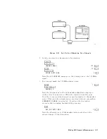
6.
Measure
the
excursion
of
the
signal
by
pressing:
4
TRACE
5
NNNNNNNNNNNNNNNNNNNNNNNNNNNNNNNN
MAX
HOLD
A
As
the
signal
varies
,
maximum
hold
maintains
the
maximum
responses
of
the
input
signal,
as
shown
in
Figure
6-10.
Figure
6-10.
Viewing
an
Unstable
Signal
Using
Max
Hold
A
Annotation
on
the
left
side
of
the
screen
indicates
the
trace
mode
.
F
or
example
,
MA
SB
SC
indicates
trace
A
is
in
maximum-hold
mode
,
trace
B
and
trace
C
are
in
store-blank
mode
.
7.
Select
trace
B
by
pressing:
4
TRACE
5
NNNNNNNNNNNNNNNNNNNNNNNNNNNNNNNNNNN
TRACE
A
B
C
B
8.
Place
trace
B
in
clear-write
mode
by
pressing:
NNNNNNNNNNNNNNNNNNNNNNNNNNNNNNNNNNNNNNNNN
CLEAR
WRITE
B
Trace
B
displays
the
current
measurement
results
as
it
sweeps
.
Trace
A
remains
in
maximum-hold
mode
,
showing
the
frequency
shift
of
the
signal.
9.
Select
trace
C
by
pressing:
NNNNNNNNNNNNNNNNNNNNNNNNNNNNNNNNNNN
TRACE
A
B
C
C
6-16
Making
EMI
Diagnostic
Measurements
Содержание 85422E
Страница 14: ...7 13 Using 3rd Ord Meas Function 7 19 12 1 External Keyboard Template 12 8 Contents 7 ...
Страница 61: ......
Страница 81: ......
Страница 116: ...Figure 6 25 Using Linearity Check to Identify Distortion Products Making EMI Diagnostic Measurements 6 35 ...
Страница 137: ......
Страница 161: ......
Страница 183: ......
Страница 195: ......
Страница 210: ...If nonrecoverable system errors occur regularly contact your HP representative Error Messages 13 15 ...
Страница 211: ......
Страница 218: ...Customer Support 14 7 ...
Страница 219: ......
Страница 229: ......


