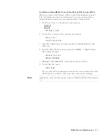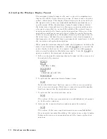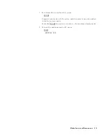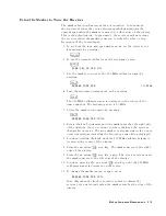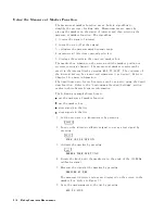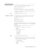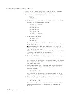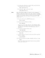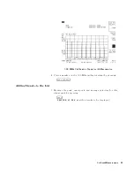
7.
T
est
the
functionality
of
limit-line
testing
using
the
internal
calibrator
signal
by
pressing:
4
INPUT
5
NNNNNNNNNNNNNNNNNNNNNNNNNNNNNNNNNNNNNNNNNNNNNNN
VIEW
CAL
ON
OFF
ON
The
message
\FAIL
MARGIN
1 "
is
displayed
because
the
calibrator
signal
exceeds
the
margin
line
.
8.
Turn
the
margin
o
by
pressing:
4
SETUP
5
N
NNNNNNNNNNNNNNNNNNNNNNNNNNNNNNNNNN
More
1
of
3
NNNNNNNNNNNNNNNNNNNNNNNNNNNNNNNNNNN
Limit
Lines
NNNNNNNNNNNNNNNNNNNNNNN
Limit
1
NNNNNNNNNNNNNNNNNNNNNNNNNNNNNNNNNNNNNNNNNNNNNNN
MARGIN
1
ON
OFF
OFF
The
message
\FAIL
LIMIT
1 "
is
displayed
because
the
calibrator
signal
now
exceeds
the
limit
line
.
9.
Turn
the
internal
calibrator
signal
o
by
pressing:
4
INPUT
5
NNNNNNNNNNNNNNNNNNNNNNNNNNNNNNNNNNNNNNNNNNNNNNN
VIEW
CAL
ON
OFF
OFF
The
message
\PASS
LIMIT "
is
displayed
because
no
onscreen
signals
exceed
the
limit
line
.
Using
Amplitude
Correction
F
actors
The
EMI
receiver
can
correct
the
displayed
data
to
take
into
account
the
eects
of
any
transducers
used
when
making
measurements
.
The
corrections
are
made
real-time
,
as
the
data
is
displayed
onscreen.
The
EMI
receiver
allows
three
types
of
amplitude-correction
factors
to
be
applied
to
the
input
signals
.
Antenna
F
actors
Conversion
factors
relating
eld
strength
to
measured
voltage
.
Cable
F
actors
Conversion
factors
to
correct
for
cable
insertion
loss
.
Other
F
actors
Correction
factors
to
account
for
the
eects
of
any
other
two-port
device
placed
between
the
antenna
and
the
receiver
.
Note
A
total
of
80
correction
frequencies
can
be
specied.
They
can
be
distributed
among
the
three
categories
in
any
combination.
A
matrix
of
correction
frequencies
and
amplitudes
is
entered
for
each
category
desired.
The
receiver
automatically
sums
the
matrices
and
applies
the
net
correction
factor
to
the
displayed
data.
The
amplitude-correction
factor
applied
to
the
lowest
selected
frequency
is
also
applied
to
all
frequencies
below
the
lowest
selected
frequency
.
The
amplitude-correction
factor
applied
to
the
highest
selected
frequency
is
also
applied
to
all
frequencies
above
the
highest
selected
frequency
.
Refer
to
Chapter
9
for
more
detailed
information.
3-10
Making
Compliance
Measurements
Содержание 85422E
Страница 14: ...7 13 Using 3rd Ord Meas Function 7 19 12 1 External Keyboard Template 12 8 Contents 7 ...
Страница 61: ......
Страница 81: ......
Страница 116: ...Figure 6 25 Using Linearity Check to Identify Distortion Products Making EMI Diagnostic Measurements 6 35 ...
Страница 137: ......
Страница 161: ......
Страница 183: ......
Страница 195: ......
Страница 210: ...If nonrecoverable system errors occur regularly contact your HP representative Error Messages 13 15 ...
Страница 211: ......
Страница 218: ...Customer Support 14 7 ...
Страница 219: ......
Страница 229: ......


